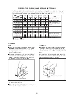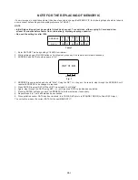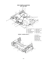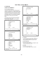
MECHANICAL ADJUSTMENTS
1. CONFIRMATION AND ADJUSTMENT
1.
2.
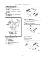
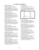
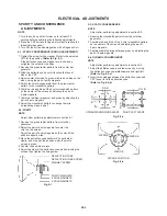
Turn on the power and set to the PLAY mode adjust the
Tension so that the Tension Post is at the position of
0.3mm~0.5mm from the Rib. (Refer to Fig. 1-2)
Confirm that the video tape is not curling at the flange of
P1 post or is not running on flanges.
1-3: CONFIRMATION AND ADJUSTMENT OF BACK
TENSION ON PLAYBACK
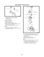
1.
2.
Load a video tape recorded in standard speed mode.
Set the unit to the PLAY mode.
Install the tentelometer as shown in Fig. 1-3.
Confirm the value is within 20~27gf at this time.
1.
2.
After adjustment, confirm and adjust the tension post
position (Refer to item 1-2) for the tension arm, install
the cassette type torque tape (JG100A) and set to the
PLAY mode.
Confirm that the left hand side tension value of the
torque tape is 25~38gf•cm for the standard mode tape.
Reel Disk (S)
Guide Roller
P1 Post
Tentelometer
Video Tape
Read the following NOTED items before starting work.
•
•
1-2: CONFIRMATION AND ADJUSTMENT OF
TENSION POST POSITION
Place an object which weighs between 350g and 500g
on the Cassette Tape to keep it steady when you want to
make the tape run without the Front Loading Unit 9. (Do
not place an object which weighs over 500g.)
When you activate the deck without the Front Loading
Unit 9, short circuit between TP1001 and Ground. In this
condition the BOT/EOT/Reel Sensor will not function.
• IN CASE OF USING A CASSETTE TYPE TORQUE TAPE.
P0 Post
Rib
Tension Post
Tension Arm
P1 Post
Tension Adjust
Fig. 1-2
Fig. 1-3
1-1: CONFIRMATION AND ADJUSTMENT OF
REEL DISK HEIGHT
Master Plane
(JG022)
Reel Disk Height
Adjustment Jig
(JG024)
Height Adjustment Washer
3.1x5.4xT0.13
3.1x5.4xT0.3
Reel Disk Height
Adjustment Jig
(JG024)
Reel Disk
Master Plane
(JG022)
7.5mm
±
0.2
B
A
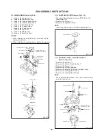
Turn on the power and set to the STOP mode.
Set the master plane (JG022) and reel disk height
adjustment jig (JG024) on mechanism framework, taking
care not to scratch the drum, as shown in Fig. 1-1-A.
Confirm that the reel disk is lower than "A" of the reel disk
height adjustment jig (JG024) on the master plane and
higher than "B" as shown in Fig. 1-1-B. If it is not, adjust to
less than 7.5mm
±
0.2mm with the height adjustment washer.
Perform the same adjustment for other reel.
1.
2.
3.
4.
Fig. 1-1-A
Fig. 1-1-B
D1-1

