DISASSEMBLY INSTRUCTIONS
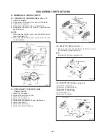
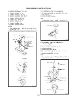
2-14: MAIN CAM (Refer to Fig. 2-14)
1.
2.
3.
4.
5.
6.
7.
8.
9.
10.
Remove the Loading Lever.
Remove the Main Brake Lever.
Remove the Capstan Brake Spring.
Remove the Capstan Brake Ass'y.
Remove the Main Rod Spring.
Remove the Tension Holder.
Remove the Tension Lever.
Remove the Main Cam.
Remove the Middle Gear.
Remove the Main Rod Ass'y.
2-15: CAPSTAN DD UNIT (Refer to Fig. 2-15)
1.
2.
3.
NOTES
1.
2.
When installing the Main Rod Ass'y, install side (B) first,
then install side (A).
When installing the Loading Lever, align the timing marks.
Middle Gear
Main Cam
Loading Lever
(B)
(A)
Main Rod Ass'y
Capstan Brake Spring
Capstan Brake Ass'y
Main Brake Lever
Main Cam
Middle Gear
Tension Lever
Main Rod Spring
Tension Holder
Loading Lever
Fig. 2-14
Loading Gear T
Marker
Disconnect the following connector: (CP4105) on the
Head Amp PCB.
Remove the 3 screws
1
.
Remove the Capstan DD Unit.
NOTE
Use the specified screw to hold the Capstan DD Unit.
Capstan DD Unit
1
1 1
Fig. 2-15
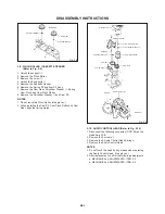
2-16: INCLINED T ASS'Y / INCLINED S ASS'Y
(Refer to Fig. 2-16)
1.
2.
3.
4.
5.
6.
7.
Remove the 4 screws
1
.
Remove the Catcher S and Catcher T.
Remove the 2 screws
2
.
Remove the 2 Slider Loadings.
Remove the Inclined T Ass'y and Inclined S Ass'y.
Remove the Loading Gear T Ass'y.
Remove the Loading Gear S Ass'y.
NOTE
When installing the Inclined T Ass'y and Inclined S Ass'y,
align the timing marks.
Loading Gear T
Loading Arm Spring
Loading Arm S Ass'y
Loading Arm Spring
Loading Arm T Ass'y
Loading Gear S
Slider Loading
Slider Loading
2
2
Inclined T Ass'y
Inclined S Ass'y
Catcher T
1
1
1
1
Marker
Loading Gear S
Loading Gear T
Fig. 2-16
Marker
Marker
Marker
Catcher S
B2-5


