Airwell GC 12 LT Скачать руководство пользователя страница 35

CONTROL SYSTEM

11-10

SM TELECOM 1-A.0 GB

11.4.3 Sequence 

Diagrams 

a.  Maintaining room temp at desired level by comparing RT and SPT with user 

defined IFAN speed.  


(RT - SPT) [

o

c]

+3

+2

+1

0

-1

-2

ON

OFF

ON

OFF

USER FAN SPEED

ON

OFF

COMP

(WVL)

OFAN

IFAN

RV


CONTENTS

Содержание GC 12 LT

Страница 1: ...SX TELECOM R410A Close Control Indoor Unit Outdoor Unit SX 12 TELECOM GC 12 LT SX 18 TELECOM GC 18 LT SX 30 TELECOM GC 30T LT JULY 2009 REFRIGERANT R410A COOLING ONLY SM TELECOM 1 A 0 GB CONTENTS...

Страница 2: ...nged pages are Original 0 June 2009 Total number of pages in this publication is 149 consisting of the following Page No Revision No Page No Revision No Page No Revision No Title 0 A 0 i 0 1 1 1 3 0 2...

Страница 3: ...UTLINE DIMENSIONS 4 1 5 PERFORMANCE DATA PRESSURE CURVES 5 1 6 ELECTRICAL DATA 6 1 7 WIRING DIAGRAMS 7 1 8 ELECTRICAL CONNECTIONS 8 1 9 REFRIGERATION DIAGRAMS 9 1 10 TUBING CONNECTIONS 10 1 11 CONTROL...

Страница 4: ...Optional Can be operated under the condition of outdoor temperature of 10 C by real pressure input Connectivity to network Airconet system control Possibility for treated air distribution to adjacent...

Страница 5: ...udes A Rotary Compressor mounted in a soundproofed compartment Axial fan Outdoor coil with hydrophilic louver fins for RC units Outlet air fan grill Service valves flare type connection Interconnectin...

Страница 6: ...MODEL REF SX 12 TELECOM SX 18 TELECOM SX 30 TELECOM GC 12 LT R410A GC 18 LT R410A GC 30T LT R410A The above tables lists outdoor units and SX indoor units which can be matched together In addition th...

Страница 7: ...6 Units per pallet units 14 Stacking height units 7 levels OUTDOOR Refrigerant control Capillary tube Compressor type model Rotary Panasonic 5PS132EAC22 Fan type quantity Propeller direct x 1 Fan spee...

Страница 8: ...Units per pallet units 14 Stacking height units 7 levels OUTDOOR Refrigerant control Capillary tube Compressor type model Rotary Panasonic 5KS205EAB21 Fan type quantity Propeller direct x 1 Fan speeds...

Страница 9: ...its 7 Stacking height units 7 Levels OUTDOOR Refrigerant control Capillary Compressor type model Rotary Mitsubishi NN33VAAMT Fan type quantity Propeller direct x 1 Fan speeds H L RPM 850 Air flow H L...

Страница 10: ...ling Indoor 27o C DB 19o C WB Outdoor 35 o C DB Heating Indoor 20o C DB Outdoor 7o C DB 6o C WB 3 1 Operating Limits R410A Indoor Outdoor Cooling Upper limit 32o C DB 23o C WB 46o C DB Lower limit 21o...

Страница 11: ...OUTLINE DIMENSIONS 4 1 SM TELECOM 1 A 0 GB 4 OUTLINE DIMENSIONS 4 1 Indoor Unit SX 12 TELECOM SX 18 TELECOM 4 2 Indoor Unit SX 30 TELECOM CONTENTS...

Страница 12: ...OUTLINE DIMENSIONS 4 2 SM TELECOM 1 A 0 GB 4 3 Outdoor Unit GC 12 LT 4 4 Outdoor Unit GC 18 LT AI R O U TLET AI R I N TAKE CONTENTS...

Страница 13: ...OUTLINE DIMENSIONS 4 3 SM TELECOM 1 A 0 GB 4 5 Outdoor Unit GC 30T LT CONTENTS...

Страница 14: ...SC 2 42 2 59 2 74 2 69 2 76 PI 0 88 0 89 0 89 0 90 0 90 30 TC 3 25 3 50 3 78 3 93 4 07 SC 2 29 2 48 2 68 2 62 2 73 PI 0 95 0 96 0 97 0 98 0 98 35 TC 3 00 3 25 3 57 3 75 3 89 SC 2 16 2 35 2 57 2 54 2 6...

Страница 15: ...between indoor and outdoor units is 3m 5 3 Pressure Curves 5 3 1 Cooling Discharge Pressure VS Outdoor Temp 10 0 20 0 30 0 40 0 15 20 25 30 35 40 46 Outdoor Temp o C DB Discharge Pressure Bar 15 21 WB...

Страница 16: ...59 3 80 3 73 3 83 PI 1 36 1 37 1 38 1 39 1 40 30 TC 4 78 5 15 5 57 5 78 5 99 SC 3 19 3 44 3 72 3 64 3 79 PI 1 47 1 49 1 51 1 52 1 52 35 TC 4 41 4 78 5 25 5 51 5 72 SC 3 00 3 27 3 57 3 53 3 67 PI 1 59...

Страница 17: ...ength between indoor and outdoor units is 3m 5 6 Pressure Curves 5 6 1 Cooling Discharge Pressure VS Outdoor Temp 10 0 20 0 30 0 40 0 15 20 25 30 35 40 46 Outdoor Temp o C DB Discharge Pressure Bar 15...

Страница 18: ...61 5 91 6 08 6 20 PI 2 30 2 32 2 34 2 35 2 37 30 TC 7 49 8 15 8 81 9 12 9 39 SC 5 12 5 44 5 78 5 95 6 07 PI 2 49 2 52 2 54 2 56 2 59 35 TC 6 93 7 52 8 30 8 72 9 13 SC 4 87 5 22 5 65 5 81 5 93 PI 2 68...

Страница 19: ...its is 3m 5 9 Pressure Curves 5 9 1 Cooling Suction Pressure Vs Outdoor Temp 5 0 6 0 7 0 8 0 9 0 10 0 11 0 12 0 15 20 25 30 35 40 46 Outdoor Temp DB o C Suction Pressure Bar g 15 21 WB DB C 17 24 WB D...

Страница 20: ...urrent A 7 6 12 3 x 9 2 Circuit Breaker 16 16 3 x 16 Power Supply Wiring No X Cross Section mm2 3x1 5 mm2 3x2 5 mm2 5 X 2 5 mm2 Interconnecting Cable RC Model No X Cross Section mm2 5x1 5 mm2 2x0 5 mm...

Страница 21: ...WIRING DIAGRAMS 7 1 SM TELECOM 1 A 0 GB 7 WIRING DIAGRAMS 7 1 Indoor Unit SX 12 7 2 Indoor Unit SX 18 SX 30 CONTENTS...

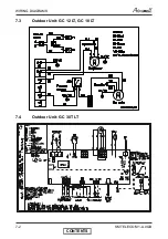
Страница 22: ...WIRING DIAGRAMS 7 2 SM TELECOM 1 A 0 GB 7 3 Outdoor Unit GC 12 LT GC 18 LT 7 4 Outdoor Unit GC 30T LT CONTENTS...

Страница 23: ...LECOM 1 A 0 GB 8 ELECTRICAL CONNECTIONS 8 1 SX 12 TELECOM GC 12 LT SX 18 TELECOM GC 18 LT 8 2 SX 30 TELECOM GC 30T LT TO ALARM SYSTEM POWER SUPPLY 1PH220 240V 50Hz CIRCULIT BREAKER NOT SUPPLIED OUTDOO...

Страница 24: ...EFRIGERATION DIAGRAMS 9 1 Heat Pump Models 9 1 1 SX 12 SX 18 Telecom 9 1 2 SX 30 Telecom OUTDOOR UNIT INDOOR UNIT Sensor Sensor Indoor coil Outdoor coil Compressor Valves connection Flared Capillary t...

Страница 25: ...Valve Protection Cap end 2 Refrigerant Valve Port use Allen wrench to open close 3 Valve Protection Cap 4 Refrigerant Valve 5 Service Port Cap 6 Flare Nut 7 Unit Back Side 8 Copper Tube When the outd...

Страница 26: ...roups of air conditioners x ST RC group Cooling only cooling and heating by heat pump x SH group Cooling and heating by heat pump and supplementary heater x RH group Cooling heating by heaters only 11...

Страница 27: ...FF HORIZONTAL VERTICAL SWING FUNCTIONS TOGETHER TEMP DISPLAY IN qF DEGREES ON DISABLE LCD KEY ILLUMINATION TIMER CLOCK 12H AM PM OFF ENABLE LCD KEY ILLUMINATION TIMER CLOCK 24H ON Reset operation Pres...

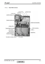
Страница 28: ...CONTROL SYSTEM 11 3 SM TELECOM 1 A 0 GB 11 1 4 Main PCB Controller CONTENTS...

Страница 29: ...5 Display Board LEXAN 11 1 6 Display Board Assembly 11 1 7 Legend A Heating LED B Cooling LED C Fan LED D Operation LED E Timer LED F Filter LED G Temp Set Point Indication H Fan Speed H High I Mediu...

Страница 30: ...LEVEL4 Overflow Level Max Maximum Min Minimum min Minute time NA Not Applicable OCP Outdoor Condensation Pump OCT Outdoor Coil Temperature RT3 sensor OF OFAN Outdoor Fan OPER Operate Para Paragraph RA...

Страница 31: ...1 3 2 IFAN operation a Min time interval between IFAN speed change in AUTOFAN Mode is 30 sec b Min time interval between IFAN speed change in H M L Mode is 1 sec c IFAN speed in Heat Cool AUTOFAN Mode...

Страница 32: ...ce after a unit is switched from OFF STBY to operation At the first occurrence of 10 min continuous COMP operation the current ICT are compared with those when the COMP was switched from OFF to ON 10...

Страница 33: ...n at the first occurrence of 15 min continuous COMP operation ICT is compared with ICT reading when the COMP was switched from OFF to ON 15 min before RV fault is defined when ICT decreases more than...

Страница 34: ...R C sensor in I FEEL mode c Indoor Coil Temp is detected by ICT d Outdoor Coil Temp is detected by OCT 11 4 2 Control Functions a COMP Operation ON OFF RT SPT 0 1 COMP b OFAN Operation x In normal ope...

Страница 35: ...ELECOM 1 A 0 GB 11 4 3 Sequence Diagrams a Maintaining room temp at desired level by comparing RT and SPT with user defined IFAN speed RT SPT o c 3 2 1 0 1 2 ON OFF ON OFF USER FAN SPEED ON OFF COMP W...

Страница 36: ...ONTROL SYSTEM 11 11 SM TELECOM 1 A 0 GB b Maintaining room temp at desired level by comparing RT and SPT with AUTO IFAN RT SPT oc 4 3 2 1 0 1 2 ON OFF ON OFF H L M ON OFF COMP WVL OFAN IFAN RV CONTENT...

Страница 37: ...ill be switched ON according to the following graph NOTE 1 When COMP is ON except WAX Model IFAN will change from LOW to OFF either when a ICT 28 and IFAN is on for 5 min or longer Or b ICT 20 NOTE 2...

Страница 38: ...rules for Heaters in RC group a Heaters can be enabled only if IFAN is ON b Heaters will operate according to T and the following graph 32 20 20 15 50 ON OFF ICT 45 HE 1 HE 2 General Window 3 Rules fo...

Страница 39: ...peration for RC and SH groups 1 As a general rule for RC and SH groups excluding protection modes OFAN starts with the compressor 2 When OFAN is ON it will operate according to the following condition...

Страница 40: ...HEAT AUTO at heating Temp Selected desired temperature Fan HIGH MED LOW Timer Any I FEEL ON or OFF 11 6 1 Sequence Diagram Maintains room temp at desired level by comparing RAT or RCT to SPT RT SPT o...

Страница 41: ...ofan Mode HEAT AUTO at heating Temp Selected desired temperature Fan AUTO Timer Any I FEEL ON or OFF 11 7 1 Sequence Diagram Maintains room temp at desired level by controlling COMP IFAN and OFAN RT S...

Страница 42: ...TO at Heating Temp Selected desired temperature Fan HIGH MED LOW Timer Any I FEEL ON or OFF 11 8 1 Sequence Diagram Maintains room temp at desired level by controlling Heating Elements HE1 or HE2 RT S...

Страница 43: ...HEAT AUTO at Heating Temp Selected desired temperature Fan AUTO Timer Any I FEEL ON or OFF 11 9 1 Sequence Diagram Maintains room temp at desired level by controlling the 2 Stage Electric Heaters RT S...

Страница 44: ...SPT 1O C or SPT 1O C respectively d For RC SH units Mode change between Auto Heat Auto Cool Modes is possible only after the COMP has been OFF during the last T minutes Mode Change Time T Auto Cool t...

Страница 45: ...r SH Groups Maintains room temp at desired level by selecting between cooling and heating modes RT SPT o c 3 2 1 0 1 2 3 4 ON OFF ON OFF H M L OFF ON OFF ON OFF COMP OFAN HE1 HE2 IFAN RV USER FAN SPEE...

Страница 46: ...L 30 sec COMP OFAN HE1 HE2 IFAN RV OFF 3 min 2 Auto Heat Mode Auto Cool Mode Auto Heat Mode 1 3 min 2 11 11 Dry Mode 11 11 1 Dry ST or RC Group or P2000 Model with Any Group Settings Mode DRY Temp Se...

Страница 47: ...than the 3 min Min COMP OFF time after every 15 min of continuous COMP operation 2 When DRY is OFF the COMP is forced ON for 6 min longer than the 3 min Min COMP ON time after every 15 min of continuo...

Страница 48: ...ure Fan LOW automatically selected by software Timer Any I FEEL Any Control function Reduces room humidity with minimum temp fluctuations by operating in Cool Mode with LOW speed IFAN and HE RT SPT o...

Страница 49: ...Fan Any Timer Any I FEEL ON or OFF Control Function Protects the indoor coil from ice formation at low ambient temperatures ICT oc 2 ON OFF ON OFF t1 t2 t3 COMP OFAN 1 5 14 0 1 ON OFF IFAN t1 t1 5 mi...

Страница 50: ...ED 52 55 61 66 L COMP is forced OFF OFAN is forced ON IFAN forced to LOW 68 OFAN follow operation of COMP COMP is forced OFF OFAN is forced ON For all models except WAX P2000 For WAX P2000 models NOTE...

Страница 51: ...rom ice formation by controlling COMP RV operation 1 Deicer Activation Algorithm a Static deicer threshold is 5 C b Dynamic deicer threshold changes of 3 C in 3 minutes in the OCT temperature c In fir...

Страница 52: ...ANY all SH units except WAX RC or WAX units HEs are forced OFF IFAN is forced to Low Speed BLINK ON OPER LED NOTES 1 In the following Deicing cycles the time interval between two Deicing cycles activ...

Страница 53: ...G Fan Any Timer Any I FEEL ON or OFF Control Function Protects the compressor from high pressure by switching OFF the OFAN and COMP ICT o c Any Off Any Off COMP OFAN 52 55 61 66 COMP is forced OFF 67...

Страница 54: ...min 8 min Overflow when unit is ON Overflow when unit is OFF 1 min Notes 1 The switch used for water level detection is closed under normal condition and is open when water overflow 2 For the NEC vers...

Страница 55: ...schedule is disabled 2 The forced operation is activated when the mode button on the Display Board is used to switch the unit to COOL or HEAT mode 3 The IFAN is always set to Autofan Speed in forced...

Страница 56: ...e from 0 to 3o C x In other modes there is no SPT adjustment x The SPT adjustment is cancelled when the Sleep mode is cancelled SPT Time Hr 4 8 5 3 2 6 Start Sleep 7 RT SPT 1 SPT 2 SPT 3 SPT 2 SPT 1 S...

Страница 57: ...starting of Sleep the Sleep time is extended And instead of going to SB at the 7th hour the A C will work until reaching the Off time Case 3 is an exception to case 2 The Sleep Mode will not be extend...

Страница 58: ...OR FAN SPEED TEST SELF TEST FLOW CHART Step 1 Step 2 Step 3 FOR CONTROLLER VERSION 4V5 OR HIGHER COOL HEAT COMPRESSOR OUTDOOR FAN R V LOW MEDIUM HIGH TIMER OPERATE STANDBY BUZZER TEST ONE BEEP SOUND R...

Страница 59: ...the remote control IR transmitter and change the temperature settings If the display indoor unit receive the settings properly the following steps will start c STEP 3 MODEL SETTING CONFIRMATION 1 The...

Страница 60: ...f STEP 5 FREQUENCY TESTING If the frequency measuring process fails the COOL LED will turn ON In order to move to the next step press ON OFF button on the remote control g STEP 6 INPUT TEST The test...

Страница 61: ...lues of Sensors Temperature VS Voltage DC Temp C Voltage V Temp C Voltage V Temp C Voltage V Temp C Voltage V 20 4 554 2 3 744 24 2 555 46 1 487 19 4 529 3 3 695 25 2 5 47 1 447 18 4 502 4 3 646 26 2...

Страница 62: ...to the following table No Problem 1 2 3 4 5 1 RT1 is disconnected 2 RT1 is shorted 3 RV fault 4 RT2 is disconnected 5 RT2 is shorted 6 Reserved 7 RT2 temp reading doesn t change 8 RT3 is disconnected...

Страница 63: ...r 5 Indoor fan works when unit is OFF and indoor fan speed is not changed by remote control command PCB problem Replace controller 6 Compressor does not start Electronics control problem or protection...

Страница 64: ...sent Wrong phase order to compressor Check compressor phase order 13 Water leakage from indoor unit Indoor unit drainage tube is blocked Check and open drainage tube 14 Freezing of outdoor unit in HEA...

Страница 65: ...EXPLODED VIEWS SPARE PARTS LISTS 13 1 SM TELECOM 1 A 0 GB 13 EXPLODED VIEWS SPARE PARTS LISTS 13 1 Indoor Unit SX 12 TELECOM SX 18 TELECOM CONTENTS...

Страница 66: ...MOUNTED BRCKET ASSY SMALL 1 14 382334 BASE EPS SMALL 1 15 307979 BACK PANEL SMALL 1 16 4520929R Motor Assy for PXD9 12 15 1 17 323425 MOTOR SUPPORT LENGTH 99 1 18 436665 STEP MOTOR 1 18 263034 SWING...

Страница 67: ...5 MOUNTED BRCKET ASSY SMALL 1 14 382334 BASE EPS SMALL 1 15 307979 BACK PANEL SMALL 1 16 4520930R Motor Assy for PXD18 1 17 323421 MOTOR SUPPORT LENGTH 119 1 18 436665 STEP MOTOR 1 18 263034 SWING MOT...

Страница 68: ...EXPLODED VIEWS SPARE PARTS LISTS 13 4 SM TELECOM 1 A 0 GB 13 4 Indoor Unit SX 30 TELECOM CONTENTS...

Страница 69: ...OTOR CABLE 1 12 293322 CENTRIFUGAL FAN BIG 2 13 466236 MOUNTED BRCKET ASSY BIG 1 14 382333 BASE EPS BIG 1 15 307980 BACK PANEL BIG 1 16 4520932R Motor Assy for PXD32 1 17 323422 MOTOR SUPPORT LENGTH 1...

Страница 70: ...EXPLODED VIEWS SPARE PARTS LISTS 13 6 SM TELECOM 1 A 0 GB 13 6 Outdoor Unit GC 12 LT CONTENTS...

Страница 71: ...lary Assy 2 6X1 4X600 GCN 12 R410A ST ASK 1 19 4510677 Nut With Flange M8 D 24 GB6187 86 3 20 391498 Wire assy 1 21 460150005R Compressor Assy 5PS132EAC22Panasonic 1 26 463750196 Dischaege Pipe Assy G...

Страница 72: ...EXPLODED VIEWS SPARE PARTS LISTS 13 8 SM TELECOM 1 A 0 GB 13 8 Outdoor Unit GC 18 LT CONTENTS...

Страница 73: ...R410A ST ASK 1 19 4510677 Nut With Flange M8 D 24 GB6187 86 3 20 391498 Wire assy 1 21 460150016R Compressor Assy Panasonic 5KS205EAB21 R410A 1 22 469270002 Insulation Rub Felt Compressor 1 26 463750...

Страница 74: ...EXPLODED VIEWS SPARE PARTS LISTS 13 10 SM TELECOM 1 A 0 GB 13 10 Outdoor Unit GC 30T LT 10 1 1 2 3 1 7 28 12 9 8 4 5 42 6 16 38 43 CONTENTS...

Страница 75: ...HANDLE CUE 1 12 433707 MOTOR SUPPORT BRACKET OU8 1 12 439775 MOTOR SUPPORT OU8 33 1 13 190443 HEATER CRANKCASE MITSUBISHI COMP 1 14 433298 COMPRESSOR NN33YCAMT 1 15 433830 CAPILLARY ASSY OU8 30 R410A...

Страница 76: ...code no RCW 436195 WNG add PCB SP000000290 ENGLISH REMOTE CONTROL 1 START STOP button 2 Operation modeselection button COOLING HEATING AUTO COOL HEAT DRY FAN 3 LOCAL temperaturesensing button 4 FAN SP...

Страница 77: ...290 1 2 3 4 1 Display screen 2 Keys for raising and lowering the set temperature 3 Ventilation mode selection Low speed Medium speed High speed AUTO Automatic speed selection 4 ON Standby Accessing th...

Страница 78: ...OPTIONAL ACCESSORIES 14 3 SM TELECOM 1 A 0 GB 14 3 RCW RCW2 Wiring Connections as Shown on Kit CONTENTS...

Страница 79: ...outdoor fan motor side Fig 2 OU7 OU8 OU10 Fig 3 Unscrew the cap of the provided service valve D and connect to the T valve supplied in the kit Use Copper sealing gasked between the flare nut and it s...

Страница 80: ...PCB Typhoon Connect Green Wire from Fan Speed Controller to Tab TB1 on PCB Typhoon Connect Y Green wire from Fan Speed Controller to ground screw on units partition Return JP1 wire previously disconn...

Страница 81: ...ether with plastic ties don t fold or break the capillary tube keep a large loop for extra length of capillary tube Check for refrigerant leaks Fig 8 Re assemble the previously removed elements Verify...

Страница 82: ...43213 MAKE SURE THAT AIR CONDITIONER IS DISCONNECTED FROM THE MAINS KIT INSTALLATION Fig 1 1 Open the return air grille by pulling both edges 2 Remove the end screws Unscrew the middle screw without r...

Страница 83: ...with the foam squares to avoid air by pass 4 Slide the heater assembly into the PXD 5 Fix the heater assembly to the supports with the supplied screws ELECTRICAL CONNECTIONS Place the wiring in the c...

Страница 84: ...RIES 14 9 SM TELECOM 1 A 0 GB MODELS SXSP 9 12 15 18 24 30 Connect the wires with 6 35 connectors directly to the control board as shown Black wire to 7 Violet wire to 7 SXSP 9 12 15 18 24 30 Blue wir...

Страница 85: ...4 10 SM TELECOM 1 A 0 GB KIT INSTALLATION Fig 3 On the unit top Using flat pliers break the plastic A for the heater cable Place the foam insulation in the groove to prevent air by pass Fig 3 A bloc m...

Страница 86: ...NG The plug has a small arrow to indicate the correct orientation The side with the arrow must be towards the back of the unit Towards the metal panel metal panel REASSEMBLY Reconnect the wiring betwe...

Страница 87: ...APPENDIX A 15 1 SM TELECOM 1 A 0 GB APPENDIX A INSTALLATION AND OPERATION MANUAL CONTENTS...

Отзывы: