CONFIDENTIAL
SERVICE MANUAL
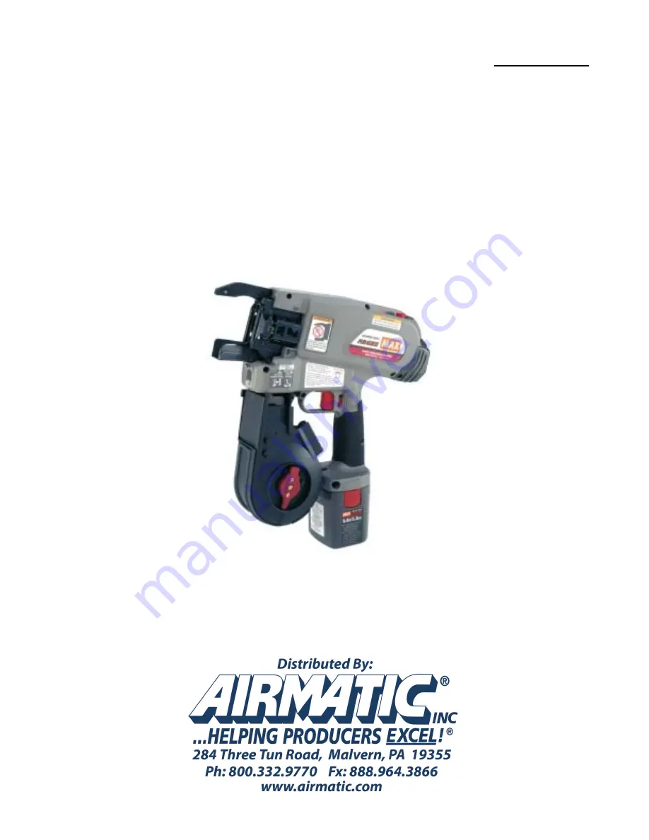
REBAR TYING TOOL
Model
:
RB655
Specifications and parts may be changed for improvement.
Страница 1: ...CONFIDENTIAL SERVICE MANUAL REBAR TYING TOOL Model RB655 Specifications and parts may be changed for improvement...
Страница 2: ...000 TIES P13 HOW TO CLEAN UP THE FEEDING GEAR AREA P17 HOW TO CLEAN UP THE CUTTER AREA P20 SELF WARM UP PROGRAM P21 HOW TO ASSEMBLE THE TOOL 1 MAIN SWITCH BASE ASSY P24 2 TWISTER ASSY FEED ASSY P30 3...
Страница 3: ...9 38 10 84 82 167 169 83 40 42 9 38 39 202 9 135 56 56 109 108 107 203 19 105 192 36 51 50 49 54 45 39 89 86 39 53 46 48 52 47 57 44 33 207 32 6 32 2 4 3 1 31 19 211 209 142 148 144 142 11 11 135 9 9...
Страница 4: ...COVER 49 AA71408 SCREW 3 X 3 115 RB70341 MAIN SWITCH UNIT 181 RB10724 SLEEVE COVER 50 EE31801 WASHER 3 2X7 116 AA31721 SCREW 3X6 182 RB11003 PROTECTOR B 51 FF41729 SETP PIN 1729 117 AA74410 SCREW 3X6...
Страница 5: ...otor of RB650A Feeding motor of RB655 is regular motor but work efficiency is improved The lifetime of the Feeding motor of RB655 is about 25 longer than the Feeding motor of RB650A Twisting Motor 70...
Страница 6: ...has better efficiency and requires less electricity NOT interchangeable with Feeding Motor of RB650A Main board and Sub board is not supplied individualy White color wire is added for running Brushle...
Страница 7: ...151 RB81032 151 RB70354 141 CE RB81105 USA RB81107 Frame R Assy 141 CE RB81069 USA RB81068 Frame L Assy 140 CE RB70119 USA RB70120 140 CE RB81104 USA RB81106 RB650A RB655 The amount of glass fiber in...
Страница 8: ...RB11883 Filter Cover Fan Protector 179 RB11886 170 RB70339 Fan Unit 170 RB81031 Picture Picture RB655 This part holds Filter A and Filter B in place Connector on Fan Unit is directly connected to the...
Страница 9: ...d fan unit to PC board 75 81 RB70369 RB70370 Twist Guide Cover L Twist Guide Cover R 75 81 RB70178 RB70179 Motor Housing Assy To improve wire pulling action the shape of the Twisg Guide Cover L and R...
Страница 10: ...ion first LED blinks only followed by number indication LED and beep Example of ties is 16 300 ties LED blinks 3 times LED Beep LED blinks 2 times LED Beep LED blinks one time LED Beep LED blinks 2 ti...
Страница 11: ...R BUTTON Press to see how many times a tool is powered on 8 ERR BUTTON Press to see total number of each error happened on a tool With pressing the button each error number will be shown in turn 1 MOT...
Страница 12: ...e connector to the Main Board of RB650 RB650A RB655 2 Power switch on Description on display Status DATA RCV READY Ready to work DAT RCV TIME OUT CMD RCV TIME OUT UNKNOW ANS RCV Error Press buttons to...
Страница 13: ...UT DRIVER 7 0 mm XB93122 SCREW DRIVER 1 XB93123 SCREW DRIVER 2 XB93124 5 SCREW DRIVER XB93125 6 TORQUE DRIVER LARGE 7 TORQUE DRIVER SMALL 8 CONNECTOR TWEEZERS Repair Tool kit Available From Max USA XB...
Страница 14: ...Cleaner then apply Molykote grease RB70351 FEEDING MOTOR The tool can not feed the wire because the brush of the Feeding Motor is worn out At initializing action feeding error beep sound may be heard...
Страница 15: ...nsor Cover from the Magazine by squeezing the two legs of the cover HOW TO CLEAN UP THE FEEDING GEAR AREA 1 4 2 Pull out the connector of the reel sensor 3 Remove the tow bolts and disassemble the mag...
Страница 16: ...olts and remove the cover of Twisting Motor 5 Pull out the connector at the feed sensor 6 Blow away dust around the gears with compressed air 7 Blow away iron powder on the magnets HOW TO CLEAN UP THE...
Страница 17: ...BB40810 50 100cN m 8 Clean up the internal gears and apply Molykote grease Then connect the feed sensor connector and reassemble the feed gears and feed motor 9 Tighgten the bolts with proper torque...
Страница 18: ...tion not to pinch BB40405 200 250cN m BB40405 200 250cN m 10 Assemble the magazine to the tool and connect the reel sensor connector then close the cover of the connector HOW TO CLEAN UP THE FEEDING G...
Страница 19: ...17 HOW TO CLEAN UP THE CUTTER AREA 1 3 1 Remove the two bolts and slide out the Cover R 2 Remove the bolt and take the Cover on the cutter area 3 Remove the pin Cutter and Fixed Cutter...
Страница 20: ...18 4 Degrease and clean up the Cutter parts Apply Molykote grease on Fixed Cutter and reassemble them HOW TO CLEAN UP THE CUTTER AREA 2 3...
Страница 21: ...19 BB40810 150 200cN m BB40425 100 150cN m HOW TO CLEAN UP THE CUTTER AREA 3 3...
Страница 22: ...e B The tie wire is not cut The self warm up program is installed to the RB650 and RB655 Running the self warm up program helps to solve the phenomenon above How to run the self warm up program Step 1...
Страница 23: ...Tapped Screw 2 x 4 Tightening torque 20 30 cN m Note The projection of the Torque Dial should be positioned as shown in the figure below ASSEMBLY PROCEDURE TORQUE ADHESIVE 20 30 cN m 10 20 cN m Not re...
Страница 24: ...the Sub board Unit 5 Insert the Rotary Switch into a Dial joint and fix the Main Switch Base and Sub board Unit with a Tapped Screw 3 x 6 Tightening torque 40 50 cN m 6 After assembling turn the Torq...
Страница 25: ...lt 3 x 8 Tightening torque 80 100 cN m Pay heed to the position of the notch in the Electrode Block and the relevant wire color If the wire is connected to the other side the Main Board Unit will be b...
Страница 26: ...kote PG 662 to Planet Gears B 3 pcs and fit them onto the pins of the Planet Cage B unit Assemble them so that you can see the grooves in the top surface of the Planet Gears 3 Apply Molykote PG 662 to...
Страница 27: ...ch at the time of assembling the C retaining ring will be deformed causing faulty operation Use snap ring pliers with stopper The opening limit dimension should be 20 2 Adjust at the stopper position...
Страница 28: ...el of the Feeding Gear Base 4 Put a Hollow Pin 1628 into a Release Lever Assy and tighten with a Special Plain Washer 5 and a Hex bolt 4 x 16 Tightening torque 100 150 cN m Note Make sure that the Rel...
Страница 29: ...n Head Screw 3 x 4 with Loctite Purple applied to it assemble a Sensor Board to a Feeding Gear Base Unit Tightening torque 50 80 cN m 3 Put a Feeding Gear Shaft A into the bearing of the Feeding Gear...
Страница 30: ...Wire Guide Base Unit with Hex bolts 3 x 5 Tightening torque 100 150 cN m Note Assemble the Feeding Gear B Unit so that the cross rib side will face upward ASSEMBLY PROCEDURE TORQUE ADHESIVE 100 150 c...
Страница 31: ...Molykote PG 662 Grease to the Planet Gears and the slideway of a Gear Retainer and set the Gear Retainer with its sagging surface on the Internal Gear side Note Make sure that the Planet Gears have n...
Страница 32: ...wn in the figure with its sagging direction facing upward 3 Make sure that the Retaining Ring is fit into the groove and that the Sensor Cover turns ASSEMBLY PROCEDURE RB81102 MAGAZINE ASSY RB10792 RE...
Страница 33: ...degreased Tapped Screw 2 x 4 to tighten it Tightening torque 10 20 cN m Note For torque control confirm that a Screw Head has seated on a board and then tighten with a Torque Screwdriver ASSEMBLY PROC...
Страница 34: ...it in until it becomes flush with the bottom surface of the Magazine 2 Apply silicone grease to a Bush A and fit it into a lower hole fit it in until it is positioned to the middle ASSEMBLY PROCEDURE...
Страница 35: ...r Plate into the boss of the Magazine 2 Push the U Shape of the Stopper Plate to fit its L Shape into the concave part of the Magazine ASSEMBLY PROCEDURE RB11777 STOPPER PLATE 1 Insert into the magazi...
Страница 36: ...ver Spring with the projection of a Magazine Cover 2 Fix the Magazine Cover Spring to the Magazine Cover with Tapped Screws 3 x 6 2 pcs Control torque after confirming that the Tapped Screws have been...
Страница 37: ...cial Plain Washer 5 1 x 12 x 1 2 directing its punched surface to the Magazine Cover side as shown in the figure 3 Assemble the Magazine Stopper and the Stopper Head with a Special Bind Screw 3 x 10 T...
Страница 38: ...e and the Magazine Cover 4 Put a Parallel Pin 1289 through the Magazine Magazine Cover and Torsion Coil Spring and push it in until the Special Rubber Washer is fit into a groove Note Confirm that the...
Страница 39: ...acklash and turn it in the counterclockwise direction with a finger tip to stop it at the 3 rd step Shift from the 1 st to the 2 nd and 3 rd step while confirming 5 Only when it is not easy to turn th...
Страница 40: ...areful not to assemble the Sensor Boards the other way around Torque should be controlled after confirming that a Screw Head has seated on the board ASSEMBLY PROCEDURE TORQUE ADHESIVE 10 20 cN m Locti...
Страница 41: ...movements of the Jaws A and B Make sure that the E Retaining Ring 2 5 has been firmly fit into a groove ASSEMBLY PROCEDURE KK33249 TORSION COIL SPRING 3249 RB10779 JAW A RB10370 JAW BASE FF41822 STEP...
Страница 42: ...figure to position 3 Tighten with a Bolt 3 x 10 Tightening torque 150 200 cN m 4 Remove the Temporary Fixing Bolt Note Pay attention to the direction of the Curl Guide B ASSEMBLY PROCEDURE TORQUE ADH...
Страница 43: ...rary Fixing Bolt through the Wire Guide B and tighten with a Hex bolt 3 x 5 Tightening torque 200 220 cN m 3 Remove the Temporary Fixing Bolt ASSEMBLY PROCEDURE TORQUE ADHESIVE 200 220 cN m Not requir...
Страница 44: ...ut 1 4 Tightening torque 200 250 cN m 7 Place the nut facing downward to dry Epoxy glue Note Make sure that the E Retaining Ring is firmly fit into a groove in the Cutter Lever Pin Ensure that the thr...
Страница 45: ...with a Bolt 3 x 16 Tightening torque 180 220 cN m 6 Remove the Temporary Fixing Bolt ASSEMBLY PROCEDURE TORQUE ADHESIVE 180 220 cN m Not required 1 Make sure that the Cutter Lever is free of epoxy gl...
Страница 46: ...s 3 x 6 Tightening torque 80 100 cN m Note Wipe off overflowing adhesive agent ASSEMBLY PROCEDURE TORQUE ADHESIVE 80 100 cN m Loctite Blue RB70036 WIRE GUIDE A2 UNIT RB10737 WIRE GUIDE A1 RB70026 ARM...
Страница 47: ...uide Base temporarily Tightening torque Approx 10 cN m ASSEMBLY PROCEDURE TORQUE ADHESIVE Approx 10 cN m Temporal tightening Not required BB40481 HEX BOLT 3 x 5 EE31127 PLAIN WASHER 3 2 x 7 RB10743 WI...
Страница 48: ...tep Pin 1729 put it through the holes in the Wire Guide Base and Wire Guide Unit and secure it with an E Retaining Ring 2 5 Note Make sure that both ends of the Compression Spring are in the dowel hol...
Страница 49: ...N m 4 Tighten further a Hex bolt 3 x 5 temporarily secured to the Wire Guide Base Tightening torque 150 200 cN m Note Wipe off overflowing adhesive agent ASSEMBLY PROCEDURE TORQUE ADHESIVE 20 30 cN m...
Страница 50: ...14 at its nose 3 Lower the Wire Guide lever to the rear end of the Wire Guide Unit to close the Wire Guide Unit 4 Check the clearance between silver pin and Arm A If it is more than 0 8mm which is di...
Страница 51: ...until the Twister Assy falls Be sure to stop unscrewing when the Twister Assy falls STEP 3 Assemble the Wire Guide Lever and confirm that the Lever moves smoothly Also make the Wire guide unit in its...
Страница 52: ...Spring and Slide Guide in that order 2 Put the unslotted end of the Sensor Rod through the upper hole in the Cover L Unit Note Watch out for the Sensor Rod direction ASSEMBLY PROCEDURE RB11667 SENSOR...
Страница 53: ...o the Magnet Holder L Unit in the direction shown in the figure 3 Set the E Retaining Ring 4 Push the Compression Spring in between the Slide Guide and the remaining slots of the Sensor Rod via the Pl...
Страница 54: ...Guide Cover L 2 Put the Twist Guide Shaft into the Twist Guide Cover L and Torsion Coil Spring 3328 Note Do not confuse the Torsion Coil Springs 3328 and 3330 with each other ASSEMBLY PROCEDURE RB107...
Страница 55: ...Cover L Position 2 Tighten the hex bolts 3 x 5 2 pcs Tightening torque 150 200 cN m 3 Confirm that opening closing the cover moves the Magnet Holder L Unit back and forth ASSEMBLY PROCEDURE BB40481 HE...
Страница 56: ...ROD KK23850 COMPRESSION SPRING 3850 1 Put the slotted end of the Sensor Rod through the Compression Spring 3850 and Slide Guide in that order 2 Put the unslotted end of the Sensor Rod through the uppe...
Страница 57: ...nit in the direction shown in the figure 3 Set the E Retaining Ring 4 Push the Plain Washer and Compression Spring in between the Slide Guide and the remaining slots of the Sensor Rod and set the E Re...
Страница 58: ...wist Guide 2 Put the Twist Guide Shaft through the Twist Guide and Torsion Coil Spring 3330 Note Do not confuse the Torsion Coil Springs 3330 and 3328 with each other ASSEMBLY PROCEDURE KK33330 TORSIO...
Страница 59: ...nto the Cover R Position 2 Tighten the hex bolts 3 x 5 2 pcs Tightening torque 150 200 cN m 3 Confirm that opening closing the Cover moves the Magnet Holder R Unit back and forth ASSEMBLY PROCEDURE BB...
Страница 60: ...o the Fan Protector from the arrow indicating the air blow direction marked side Ensure that the name label air blow direction indicating arrow of the Fan Unit is directed to the opening side of the M...
Страница 61: ...t a Filter A and a Filter B into a Filter Cover in that order 2 Fit the assembly made in Step 1 into the Motor Housing L as shown in the figure ASSEMBLY PROCEDURE RB11883 FILTER COVER RB11885 FILTER B...
Страница 62: ...tor Sensor Harness coming from the Twisting Motor and three yellow blue and white harnesses as shown in the figure 3 After assembling confirm that the Twisting Motor is properly fit into the Motor Hou...
Страница 63: ...n the direction shown in the figure Note that it has directionality 2 Attach the Motor Housing R with the assembled Fan Protector to the Motor Housing L There should be no gap allowed between the Moto...
Страница 64: ...tep 1 Assemble a JAW Base Assy to the Frame L with Hex Bolts 3 x 8 Tightening torque 100 150 cN m ASSEMBLY PROCEDURE TORQUE ADHESIVE 100 150 cN m Not required BB40410 HEX BOLT 3 x 8 RB70033 JAW BASE A...
Страница 65: ...3 x 10 2 For the side where a Hollow pin has been press fit into the Frame L set a Plain Washer 2 3 and fix with a Bolt 3 x 10 Tightening torque 100 150 cN m ASSEMBLY PROCEDURE TORQUE ADHESIVE 100 15...
Страница 66: ...rt of a Torsion Coil Spring 3329 onto the cylindrical part of a Cutter Shaft and hook the straight part of a spring leg onto the Arm Setscrew and its arc part into a groove in a Cutter Lever pin 5 Aft...
Страница 67: ...ss 11P Unit and the Harness 7P Unit from the back of the Main Board Unit as shown in the figure ASSEMBLY PROCEDURE RB70084 HARNESS 11P UNIT RB70085 HARNESS 7P UNIT RB70075 MAIN BOARD UNIT MAIN SWITCH...
Страница 68: ...ness of the Trigger Switch as with the harness 7P unit and fit the Trigger Switch into the boss of the Frame L 5 Put the harness 11P unit coming from the Main Board unit through a notch ASSEMBLY PROCE...
Страница 69: ...ard between the frame L and the sub board through the notch followed by Area B to wire it as shown in the figure 7 Wire a red harness coming from the Main Switch Unit as shown in the figure 8 Assemble...
Страница 70: ...ft Guide 3P Sensor Board E Unit Pawl Base GREASE MOLYKOTE PG 662 Putting Harness 11P Unit through After inserting into the connector put the harness through the notch of the arm shaft guide Notch of A...
Страница 71: ...ble the Arm Shaft Assy to the Frame L Fit the Sleeve Guide Arm Shaft Guide Internal Gear B and Motor Gear B unit into the ribs of the Frame L Fit the straight section of the Cutter Ring into the groov...
Страница 72: ...arness red and through a notch in the sub board to connect to the sub board Lay out the terminals in order of yellow blue and white from the bottom WHITE BLUE YELLOW HARNESS WHITE SUB BOARD FN UNIT CO...
Страница 73: ...g the Motor Shaft confirm that the Motor Assy is properly fit into the Frame L 3 Pass the Fan Unit connector under the harness red of the Main Switch to connect it to the Fan connecting terminal of th...
Страница 74: ...Washer 5 1 x 9 onto the boss of the Frame L as shown in the figure 1 place 3 Assemble a Frame R assy to the Frame L ASSEMBLY PROCEDURE RB10854 TRIGGER KK23656 COMPRESSION SPRING 3656 RB10855 TRIGGER L...
Страница 75: ...fix them with two 3 x 10 bolts The bolts and should be put through the Plain Washer 2 3 Tightening torque 100 150 cN m 40 60 cN m Others 50 100 cN m Note Tighten the bolts in order of to ASSEMBLY PROC...
Страница 76: ...550VF unit and assemble it to an Internal Gear and then to the Frame Assemble a Motor stopper and the Internal Gear to the rib of the Frame L and a Feed Gear Base to the rib of a Frame R ASSEMBLY PRO...
Страница 77: ...over over them 3 Fix the Motor Cover with 3 Bolts 3 x 10 to on the Frame L side and 1 Bolt 3 x 16 on the Frame R side Put the Bolt through a Plain Washer 2 3 Tightening torque 100 150 cN m Others 50 1...
Страница 78: ...a groove in the Frame L as shown in the figure 3 Connect the connector of the Harness 4P coming from the frame to the sensor Board F Unit 4 Fit the pawl of the Sensor Cover into the square hole in th...
Страница 79: ...roblem happens on wire feeding action Or problem happens on sensor at the Feeding gear 4 Bip bip bip bip bip bip bip bip Quadruple repetitive sound Sensor in the Magazine can not sense the notches on...
Страница 80: ...nd new one No The PC boards can not detect the rotation of the Twisting Motor Connect the connector and wire harnesses firmly Yes Twisting Motor is locked Or Twister is locked Remove foreigh substance...
Страница 81: ...it is broken 2 Twister is locked 1 Replace Harness 11P unit with a new one 2 Remove foreign substances which lock Twister No Tie wire got entangled around the Hooks Remove the tie wire from the Hooks...
Страница 82: ...s of the wire reel 3 Harness 7P unit is cut or Sensor board F unit is broken 1 Connect the connectors firmly 2 Clean up the photo sensor inside of the reel magazine with cotton swab 3 Replace the Harn...
Страница 83: ...ip of the wire reaches the room between the Hook L and the Center Hook The Sensor at the Feeding Motor stops feeding action when approx 12 13 of wire is fed Hook L closes and catch the tip of the tie...
Страница 84: ...to cut the tie wire 4 TWISTING Just after the Cutter cuts the wire the Hook L R starts rotating action and the wire is kept twisted 5 RELEASING When the Main PC board senses the tightness is good eno...
Страница 85: ...1 MAIN SWITCH UNIT 50 EE31801 WASHER 3 2X7 10 116 AA31721 SCREW 3X6 51 FF41729 SETP PIN 1729 117 AA74410 SCREW 3X6 52 KK23849 COMP SPRING 3849 20 118 RB10400 LEAF SPRING 53 RB10737 WIRE GUIDE A1 119 R...
Страница 86: ...172 RB11885 FILER B 173 RB11004 PROTECTOR C 174 EE39830 WASHER 5 1X 9 175 RB11777 STOPPER PLATE 176 RB10718 SLEEVE GUIDE 177 RB11762 HOOK L 178 RB11763 HOOK R 179 RB11886 FAN PROTECTOR 180 RB11883 FIL...
Страница 87: ...36 36 36 99 8 106 56 36 87 57 56 56 36 49 48 57 142 142 143 10 56 67 36 36 143 57 56 56 57 56 57 134 56 134 130 183 10 116 TIGHTENING TORQUE CHART 85 200 220 150 200 100 150 80 100 50 80 40 50 20 30 1...