


Ultima Compact™
Chillers
43
Ultima Compact 30-150kW Technical Manual 9690553 V1.2.0_10_2019
Installation
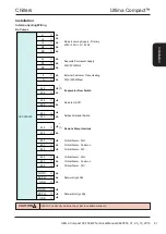
Anti Vibration Mounting (Optional)
Spring Type
Each mount is coloured to indicate the different loads, refer to AV selection sheet
supplied separately for correct allocation.
B
A
C
D
E
F
E
A
(1)
(mm)
B (mm)
C (mm)
D (mm)
E (mm)
FØ (mm)
2 Spring
162
110
180
148
16
11
1) Unloaded dimension.
2
1
6a
5
6b
10
9
8
7
3 4
Components
1
Locating screw
2
Retaining nut & washer
3
Levelling screw
4
Levelling lock nut
5
Retaining studs
6a
Upper retaining nuts
6b
Lower retaining nuts
7
Spring assembly
8
Pressure plate
9
Top plate
10 Fixing holes
Installation
1
Locate and secure mount using fixing holes (10) in base plate.
2
Ensure mounts are located in line with the unit base.
3
If applicable, remove compressor enclosure covers to allow access to mount fixing holes in the unit base.
4
Lock the upper retaining nuts (6a) to the underside of the top plate (9) before a load is applied.
5
Slacken levelling lock nut (4). (The levelling screw will not move if this is not slackened).
6
Remove retaining nut and washer (2), lower the unit onto the mounts and replace retaining nut and washer.
7
Beginning with the mount with the largest deflection, adjust the height of each mount using the levelling screw
(3). Mountings must be adjusted incrementally in turn.
8
Do not fully adjust 1 mount at a time as this may overload and damage springs.
9
When all mounts are level, lock each into place using the levelling lock nut (4).
10
Lock all retaining nuts (6a and 6b) to the extreme ends of the retaining studs (5).
Do not connect any services until all anti vibration mounts have been fully adjusted.
CAUTION
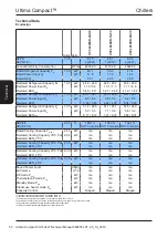
Pad Type
1
2
3
2 5
4
3
6
7
1
M16 Bolt (Not Supplied)
2
Washer (Not Supplied)
3
Fixing Pad 6173231
4
A V Pad 6173223
5
2 x M16 Nut (Not Supplied)
6
Unit Base
7 Unit Mounting Plinth
Installation (steel plinth)
1. Locate the pad type anti vibration mount between the unit base and the unit steel mounting plinth.
2. Locate the M16 bolt through the hole in the unit, AV mount pad and steel mounting plinth.
3. Tighten the M16 nut to the underside of the steel mounting plinth.
4. Tighten the second M16 nut (locking nut) to the underside of the steel mounting plinth.
Installation (concrete plinth)
1. Locate the pad type anti vibration mount between the unit base and the unit concrete mounting plinth.
2. Locate the concrete fixing anchor through the AV mount pad and the hole in the unit.
3. Tighten the anchor bolt.
Ins
ta
lla
tio
n