


Ultima Compact™
Chillers
30 Ultima Compact 30-150kW Technical Manual 9690553 V1.2.0_10_2019
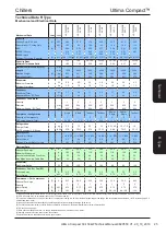
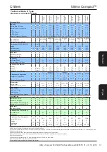
Table 5
16
18
20
22
24
26
28
30
Mechanical Data
Notes Units
UCCL050DX-
2ADD
UCCL060SX-
2AK0
UCCL060DX-
2AEE
UCCL070SX-
2AL0
UCCL070DX-
2AFF
UCCL075SX-
2AM0
UCCL075SX-
2AP0
UCCL075DX-
2AGG
Capacity
Cooling Duty - EC Fans
(1)
kW
49.5
53.9
54.8
60.9
61.7
67.8
83.7
69.1
Nominal Input - Cooling Only
kW
16.9
20.2
19.9
22.9
22.5
27.7
38.5
27.1
EER
(2)
2.92
2.67
2.75
2.65
2.74
2.45
2.17
2.55
ESEER (Gross)
3.48
3.81
3.34
3.76
3.28
3.61
3.62
3.10
ESEER (Nett)
3.35
3.66
3.22
3.62
3.16
3.48
3.39
2.99
Minimum Turndown (Capacity)
(3)
kW
23.4 / 45% 28.8 / 55% 26.1 / 50% 32.7 / 55% 29.5 / 50% 37.2 / 55% 32.9 / 40% 33.0 / 50%
Capacity Steps
%
45-100
55-100
50-100
55-100
50-100
55-100
40-75-100
50-100
Minimum Turndown Ratio
0.47
0.53
0.48
0.54
0.48
0.55
0.39
0.48
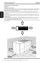
Dimensions (H 1450 x W 1310)
mm
Length
mm
2500
2500
2500
2500
2500
2500
2500
2500
Machine Weight
(4)
kg
666
670
672
680
680
686
686
686
Operating Weight
kg
675
684
684
695
693
701
701
700
Evaporator
Maximum Waterflow
l/s
4.3
4.8
4.9
5.4
5.5
6.0
7.3
6.2
Minimum Waterflow
l/s
1.3
1.5
2.1
1.7
2.3
1.9
1.9
2.6
Condenser
Face Area (Total)
m²
3.4
3.4
3.4
3.4
3.4
3.4
3.4
3.4
Nominal Airflow - EC Fans
m³/s
6.7
6.7
6.7
6.7
6.7
6.7
6.7
6.7
Condenser Fan & Motor
Quantity
2
2
2
2
2
2
2
2
Diameter
mm
710
710
710
710
710
710
710
710
Maximum Speed - EC Fans
rpm
750
750
750
750
750
750
750
750
Compressor Configuration
Tandem
Single
Single
Tandem
Single
Tandem
Trio
Single
Quantity of Compressors
2
2
2
2
2
2
3
2
Oil Charge Volume (Total)
l
2 x 3.3
1 x 3.3 + 1
x 3.3
1 x 3.3 + 1
x 3.3
2 x 3.3
1 x 3.3 + 1
x 3.3
2 x 3.3
3 x 3.3
1 x 3.3 + 1
x 3.3
Refrigeration
Charge (Total)
kg
15
15.5
8 + 8
15.5
8 + 8
16
16
8 + 8
GWP Equivalent C0
2
Tonnes
tC02
10.13
10.46
10.80
10.46
10.80
10.80
10.80
10.80
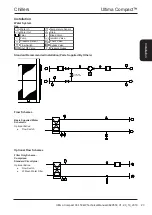
Water System
Water Inlet / Outlet
2” BSP
2” BSP
2” BSP
2” BSP
2” BSP
2” BSP
2” BSP
2” BSP
Water Volume
l
9.3
12.7
14.6
13.1
15.0
15.0
13.5
Minimum System Water Volume
(5)
l
538
550
688
620
779
691
692
Electrical Data
Nominal Run Amps
(6)
A
41.1
44.1
44.1
47.4
47.4
52.7
68.4
52.7
Maximum Start Amps
A
165
167
167
173
173
187
194
187
Recommended Mains Fuse Size
A
50
50
50
63
63
63
80
63
Max Mains Incoming Cable Size
mm²
35
35
35
35
35
35
35
35
Evaporator
Pad Heater Rating
W
80
100
80
100
80
100
100
80
Condenser Fan - Per Fan (EC)
Full Load Amps
A
2.7
2.7
2.7
2.7
2.7
2.7
2.7
2.7
Motor Rating
kW
1.7
1.7
1.7
1.7
1.7
1.7
1.7
1.7
Compressor - Per Compressor
Nominal Run Amps
(7)
A
41.1
44.1
44.1
47.4
47.4
52.7
68.4
52.7
Quantity
2
2
2
2
2
2
2
2
Motor Rating
(7)
kW
1.7
1.7
1.7
1.7
1.7
1.7
1.7
1.7
Start Amps
(8)
A
142 / 142
142
142 / 142
147
147 / 147
158
147
158 / 158
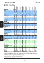
Table 6
32
34
36
38
40
42
44
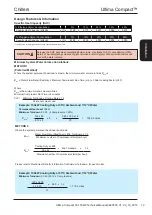
(1) Based on units performance at 12/7°C return/supply temperature, 35ºC ambient,100% water. All performance data supplied in accordance with BS EN 14511-1:2018.
(2) EER is Cooling duty / (Compressor input power + Fan input power).
(3) Turndown is based on the minimum number of compressors running in a 35°C ambient whilst operating at the design flow rate determined at full load, 12/7°C return/supply, 35°C
ambinet and 100% water.
(4) Based on standard unit without options, operating weight includes refrigerant charge guide value.
(5) For minimum system volume, refer to Design Features & Information - Minimum System Water Volume Calculations.
(6) EC fans and no pumps.
(7) Data quoted at design flowrate, 7°C supply temperature and 35°C ambient, 100% water.
(8) Starting amps refers to the direct on line connections.
Pump electrical data is available from Airedale upon request.
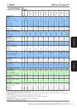
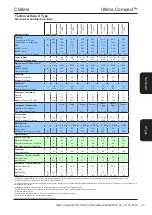
Technical Data X Type
Mechanical and Electrical Data
Te
ch
ni
ca
l
R
-T
yp
e
X -
Ty
pe