3-2
EB AT-RP-4GU EN
Design and principle of operation
3.2 Complementary/accessory parts
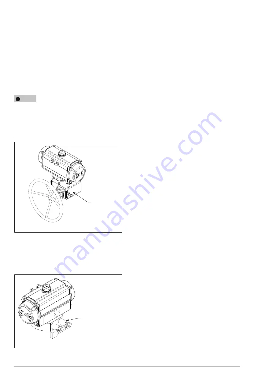
Gearbox
It is an emergency manual override system designed to
provide manual operation to drive the actuator and the valve
in the safe position when the supply pressure is not available
in case of any emergency situation. The actuator and the
valve are operated rotating a handwheel. (Fig. 3-4)
Î
Refer to the gearbox instruction manual available from
AIR TORQUE.
Risk of actuator damage due to incorrect gearbox stroke
adjustment.
−
Make sure that the actuator and the gearbox are correctly
oriented, with reference to the rotation direction required.
−
Make sure that the stroke of the gearbox does not exceed
the stroke allowed by the actuator.
Fig. 3-4
GEARBOX
Block and safety lock-out system
The block and safety lock-out system permits to lock the actua-
tor and the valve in specific cases, despite the fail action of
the actuator. (Fig. 3-5)
Î
Refer to technical data T.D.S. 4.3.1.
Fig. 3-5
BLOCK AND SAFETY
LOCK-OUT SYSTEM
NOTICE
!
3.3 Technical data
The nameplate provides information on the actuator configu-
ration.
Î
Refer to section 2.1 ‘Actuator nameplate sample‘.
Î
More informations are available in the actuator model
technical data sheet available from AIR TORQUE.
Power operating media
−
Use dry or lubricated air or inert gas.
−
Make sure the operating media is compatible with the ac-
tuator internal parts and lubricant.
−
In case of pressure medium different than Group 2 fluids
according to the PED 2014/68/EU, contact AIR TOR-
QUE.
−
The operating media must have a dew point equal to
–20°C (-4°F) or at least 10°C (18°F) below the ambient
temperature.
−
The maximum particle size contained into the operating
media must not exceed 30 μm.
Supply pressure
−
The maximum operating pressure is 8 bar (116 Psi).
Î
Refer to section 2.1 ‘Actuator nameplate sample‘ (Table
2-1, position 05).
−
For double acting and single acting actuators the working
pressure is from 2.5 bar (36 Psi) to 8 bar (116 Psi).
Î
Refer to the actuator model technical data for output tor-
que values related to the working pressure range.
Operating temperature
The nameplate provides indication on the operating tempera-
tures.
– “ST” actuators for standard temperatures from
-40°C (-40°F) to +80°C (+176°F).
– “HT” actuators for high temperatures from
-15°C (+5°F) to +150°C (+302°F).
– “LLT2” actuators for extremely low temperatures from
-60°C (-76°F) to +80°C (+176°F).
Î
Refer to the data sheet RP10600E for the soft spare parts
material and lubricant type in relation to the different wor-
king temperature ranges.
Stroking time
The stroking time depends on several factors such as supply
pressure, supply system capacity (tubing diameter, pneumatic
accessories flow capacity), valve type, valve torque, applied
safety factor, cycle frequency, temperatures, etc. Nevertheless,
an indication of the stroking time in clearly defined conditions
is available in the actuator model technical data sheet.
Содержание AT045U
Страница 4: ...4 EB AT RP 4GU EN...
Страница 8: ...1 4 EB AT RP 4GU EN Safety instructions and measures...
Страница 10: ...2 2 EB AT RP 4GU EN Markings on the device...
Страница 18: ...5 4 EB AT RP 4GU EN Mounting and assembly...
Страница 20: ...6 2 EB AT RP 4GU EN Start up...
Страница 22: ...7 2 EB AT RP 4GU EN Operation...
Страница 24: ...8 2 EB AT RP 4GU EN Malfunctions...
Страница 37: ...10 2 EB AT RP 4GU EN Decomissioning...
Страница 41: ...12 2 EB AT RP 4GU EN Repairs...
Страница 43: ...13 2 EB AT RP 4GU EN Disposal...
Страница 45: ...14 2 EB AT RP 4GU EN...
Страница 50: ...EB AT RP 4GU EN 15 5 Annex...
Страница 51: ...15 6 EB AT RP 4GU EN...
Страница 52: ...EB AT RP 4GU EN 15 7...


