Page 30
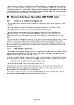
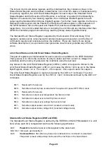
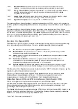
Bit 4
Execution Error.
Set when a non-zero value is written to the Execution Error
register, if a syntactically correct command cannot be executed for any reason.
Bit 3
Verify Timeout Error.
Set when a parameter is set with 'verify' specified and the
value is not reached within 5 secs, e.g. output voltage is slowed by a large
capacitor on the output.
Bit 2
Query Error.
Set when a query error occurs, because the controller has not issued
commands and read response messages in the correct sequence.
Bit 0
Operation Complete.
Set in response to the ‘*OPC’ command.
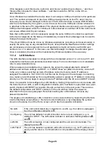
The Standard Event Status Register is read and cleared by the *ESR? query, which returns a
decimal number corresponding to the contents. On power-up it is set to 128, to report the power
on bit.
The Standard Event Status Enable Register provides a mask between the Event Status
Register and the Status Byte Register. If any bit becomes ‘1’ in both registers, then the ESB bit
will be set in the Status Byte Register. This enable register is set by the *ESE <
NRF
> command
to a value 0 - 255, and read back by the *ESE? query (which will always return the value last
set by the controller). On power-up it is set to 0.
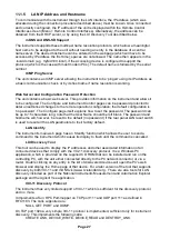
Execution Error Register (EER)
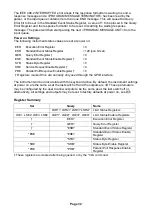
This instrument specific register contains a number representing the last command processing
error encountered over this interface. The error numbers have the following meaning:
The Execution Error Register is read and cleared using the ‘EER?’ command. On power up this
register is set to 0 for all interface instances.
There is no corresponding mask register: if any of these errors occurs, then bit 4 of the
Standard Event Status Register will be set. This bit can be masked from any further
consequences by clearing bit 4 of the Standard Event Status Enable Register.
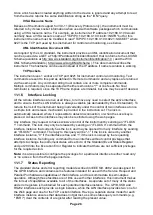
Status Byte Register (STB) and GPIB Service Request Enable Register (SRE)
These two registers are implemented as required by the IEEE Std. 488.2.
Any bits set in the Status Byte Register which correspond to bits set in the Service Request
Enable Register will cause the RQS/MSS bit to be set in the Status Byte Register, thus
generating a Service Request on the bus.
The Status Byte Register is read either by the *STB? query, which will return MSS in bit 6, or by
a Serial Poll which will return RQS in bit 6. The Service Request Enable register is set by the
*SRE <
NRF
> command and read by the *SRE? Query.
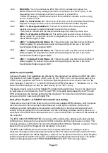
Bits 7 & 3 :
Not used, permanently 0.
0
No error has occurred since this register was last read.
100
Numeric Error:
the parameter value sent was outside the permitted range for the
command in the present circumstances.
102
Recall Error:
a
recall of set up data has been requested but the store specified does
not contain any data.
103
Command Invalid:
the command is recognised but is not valid in the current
circumstances. Typical examples would by trying to change V2 directly while the
outputs are in voltage tracking mode with V1 as the master.
200
Access Denied:
an attempt was made to change the instrument’s settings from an
interface which is locked out of write privileges by a lock held by another interface.

