16
RC SERIES INSTALLATION MANUAL
Installation Steps cont.
1
Top view
Side view
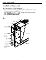
Figure 3
2
Field Converting Console
Chassis is normally configured with controls on right end and piping on left end (see Figure 3 top view). In this position panel number 1
would be positioned against wall or back plate. Unit may also be turned 180° against wall or back plate. In this position controls will be
on left end and piping on right end panel number 2 would be positioned against wall or back plate. Chassis must be enclosed with an
approved cabinet enclosure.
Remove 4 screws from front kick panel on cabinet.
1.
Remove cabinet from chassis by lifting and sliding cabinet
2.
straight up.
Remove grille assembly from cabinet by removing 4 screws from
3.
brackets located on the bottom of the grille and door assemblies.
Replace grille/door assemblies into cabinet repositioning pieces
4.
1, 2, and 3 into the locations directly opposite the original positions.
Secure by replacing mounting brackets. (Note: Be sure that louvers
on the grille assembly are facing the proper direction when
replacing the grille section.)
Replace grille/frame assembly into cabinet, and secure by replacing
5.
mounting brackets.
Replace cabinet by sliding it down over the top of the chassis.
6.
Remove tab on leg that extends into return air opening. When the
7.
grille side of the cabinet is flat against chassis there will be 4
holes that line up in the leg section. Only use 1 hole for alignment
for opposite side of grille. (Note: The tab can be removed by
twisting back and forth until it breaks off.)
Remove plastic strip from tab and replace on rough edge that the
8.
tab was removed from.
Replace screws in font kick panel to secure cabinet to chassis.
9.
Mount filter bracket in designated opening area. (Note: The filter
10.
bracket will only fit in one direction if cabinet is installed properly.)
Figure 4
4
2
1
3
5
Depends on Cabinet Size


