34
RC SERIES INSTALLATION MANUAL
Controls - FX10 cont.
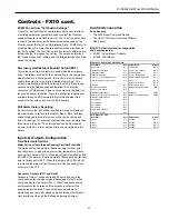
FX10 User Interface (MUI) Physical Layout
Power LED
LED 1
LED 4
Escape (ESC)
Button
Return Button
Alarm LED
LED 8
Up Arrow
Right Arrow
Left Arrow
Down Arrow
Alarm LED -
Indicates a
Lock-Out
or a bad
Freeze Sensor
Power LED -
Shows FX processor is operational
LED 1 -
Flashing shows
Compressor 1
running
LED 2 -
Flashing shows
Full Capacity Compressor
running
LED 3 -
On shows
Fan
running
LED 4 -
On shows
Reversing Valve
in cool
LED 8 -
Flashing shows unit in ‘
Test’ Mode
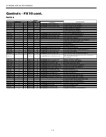
MUI Menu Navigation for Single Compressor - RC Series Water-to-Air
Welcome
Info Status Temps Outputs Settings Maint Alarms Alm-History
PROFXENV-XX
3/8/07
Info
Run Mode
Auto
Eff Occup’y
Occ
Y1 Input
OFF
Y2 Input
OFF
G Input
OFF
O Input
OFF
Occ Input
Occ
Temp Occ Inp
OFF
Condensate
NML
Emg Input
Run
Lo Press
ON
Hi Press
ON
Rndm Tmr
0
BI-4 Input
OFF
Status
Zone Temp
77.2 ºF
Dis Air Temp
51.0 ºF
Eff Clg Setpt
70.0°F
Eff Htg Setpt
66.0°F
Water Coil
77.8°F
Low WC Limit
30.0°F
Humidity
56.7 %RH
WarmCool AI
14.6
WarmCoolAdj
0.2
Temps
nvoFanStatus
ON
CmpCmd Status OFF
Cmp Capacity
OFF
Rev Valve
Heat
X1 Output
OFF
X2 Output
OFF
PWMOut
98%
BO5
OFF
BO9
OFF
AO2 Output
0%
Outputs
Settings
Unit of Measure
F
Occ Clg Setpt
73.9 ºF
Occ Htg Setpt
69.9 ºF
Unocc Clg
84.0 ºF
Unocc Htg
60.0 ºF
DeHumSetpt
0%
SensorSelect
TAXXJ02


