


K65C/K75C/K95C
4-5
K65C/K75C/K95C
4-5
Fuel supply system
The fuel tank is located on the right-
hand side of the loader rear. An
electrical fuel gauge (4-13/7) in the
operator’s cabin monitors the fuel
level in the tank. The filler neck
(4-6/arrow) is located on the right
side in the cabin access area.
Air filter device
Dry air filter device with safety
cartridge and dust discharge valve.
Lift and tip devices
- Two lift cylinders and
- one tip cylinder
are fed by a double-acting gear-
type pump via a control valve.
All movements of the bucket arm,
the bucket, the attachments and the
quick-change device are controlled
from the operator’s seat by pilot
valves.
The pilot valves provide continuous
speed control from “slow” to “fast”.
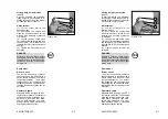
Float position
The loader is equipped with a
floating position function which
allows work such as levelling
(grading) to be carried out in a
rough terrain. To use this function,
the hand lever for the working
h y d r a u l i c s ( 4 - 1 2 / 5 ) m u s t b e
pressed beyond its pressure point
into the forward position. The hand
lever remains in this position until
the bucket arm is to be lifted again
by moving the hand lever into the
opposite direction.
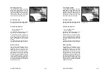
Figure 4-6
Fuel supply system
The fuel tank is located on the right-
hand side of the loader rear. An
electrical fuel gauge (4-13/7) in the
operator’s cabin monitors the fuel
level in the tank. The filler neck
(4-6/arrow) is located on the right
side in the cabin access area.
Air filter device
Dry air filter device with safety
cartridge and dust discharge valve.
Lift and tip devices
- Two lift cylinders and
- one tip cylinder
are fed by a double-acting gear-
type pump via a control valve.
All movements of the bucket arm,
the bucket, the attachments and the
quick-change device are controlled
from the operator’s seat by pilot
valves.
The pilot valves provide continuous
speed control from “slow” to “fast”.
Float position
The loader is equipped with a
floating position function which
allows work such as levelling
(grading) to be carried out in a
rough terrain. To use this function,
the hand lever for the working
h y d r a u l i c s ( 4 - 1 2 / 5 ) m u s t b e
pressed beyond its pressure point
into the forward position. The hand
lever remains in this position until
the bucket arm is to be lifted again
by moving the hand lever into the
opposite direction.
Figure 4-6
Содержание AL 65
Страница 8: ...Safety regulations...
Страница 29: ...Signs...
Страница 38: ...Technical data...
Страница 60: ...Description...
Страница 72: ...Operation...
Страница 83: ...Attachments...
Страница 91: ...Rescue towing lashing lifting by crane...
Страница 100: ...Maintenance...
Страница 120: ...Malfunctions causes and remedies...
Страница 123: ...Protection against theft...
Страница 126: ...Appendices...
Страница 127: ......
Страница 128: ......
Страница 131: ......
Страница 133: ...K65C K75C K95C K65C K75C K95C A 11 3 Muster Pr fhinweise f r Schaufellader A 11 3 Muster Pr fhinweise f r Schaufellader...
Страница 134: ...K65C K75C K95C K65C K75C K95C B B...
Страница 135: ...K65C K75C K95C K65C K75C K95C C C...
Страница 136: ...K65C K75C K95C K65C K75C K95C D D...
Страница 137: ...K65C K75C K95C K65C K75C K95C E E...
Страница 138: ...K65C K75C K95C K65C K75C K95C F F...


