background image

K65C/K75C/K95C

K65C/K75C/K95C

F

F

Содержание AL 65

Страница 1: ...chsbrunnen 2 Telefax 04331 351404 Ahlmann Baumaschinen GmbH D 24782 B delsdorf Telefon 04331 351 325 Am Friedrichsbrunnen 2 Telefax 04331 351404 AL 65 75 95 AL 65 75 95 1004319A OPERATING INSTRUCTIONS...

Страница 2: ...by the manufacturer there may be differences in the figures however this has no influence on the technical contents Introduction Preface Ahlmann sswivelshovelloaders articulatedloadersandloaderexcava...

Страница 3: ...ons StVZO Stra enverkehrzulassungsordnung German Traffic Regulations opt optional equipment Edition 06 98 Print 04 99 How to handle this manual Explanations The designations left and right are to be s...

Страница 4: ...stem 3 2 3 1 9 Brake system 3 2 3 1 10 Electrical system 3 2 3 1 11 Hydraulic system 3 3 3 1 12 Fuel supply system 3 3 Table of contents 1 Fundamental safety instructions 1 1 1 1 Warnings and symbols...

Страница 5: ...1 Buckets 3 10 3 4 2 Fork lift attachment 3 12 3 4 3 Lifting hook 3 12 3 5 Attachments AL 75 3 14 3 5 1 Buckets 3 14 3 1 13 Heating and ventilation system 3 3 3 1 14 Return flow suction filter 3 3 3...

Страница 6: ...smounting attachments with a hydraulic connection 6 4 6 2 1 Multi purpose bucket 6 4 6 3 Using other attachments 6 7 3 5 2 Fork lift attachment 3 16 3 5 3 Lifting hook 3 16 3 6 Attachments AL 95 3 18...

Страница 7: ...1 Identifying features on the loader 10 1 10 2 Parking the loader 10 1 10 3 Transponder for drive away interlock 10 2 7 Rescue towing lashing lifting by crane 7 1 7 1 Rescue towing lashing 7 1 7 1 1 R...

Страница 8: ...Safety regulations...

Страница 9: ...e use of the machine may cause danger for the user or third parties or impairments to the machine or other real values 1 Fundamental safety instruction 1 1 Warningsandsymbols In this operation manual...

Страница 10: ...nvironment protection must be observed and the personnel must be accordingly Traffic regulations must also be observed 1 2 2 The machine and attach mentsmayonlybeusedinatechnical non objectionable con...

Страница 11: ...ce the safety of the machine stop the machine immediately and inform the competent person in charge about the incident 1 3 3 The personnel in charge of workingwiththemachinemustread the operating manu...

Страница 12: ...on strated their ability to their em ployer must be expected to carry out the work conveyed to them in diligent manner 1 3 9 Without the manufacturer s consent do not make any modifications or convers...

Страница 13: ...ng 1 5 1 5 Before moving the machine always check that the attachments are safely stowed so that no accident may occur 1 4 2 Electrical work on the machine may only be carried out by a qualified elect...

Страница 14: ...byworkattachmentsanddevices by loads swiveling out by loads falling down by attachments falling down from the machine 1 5 1 6 Beforecommencingwork make yourself familiar with the working environment...

Страница 15: ...safe execution of certain work additio nal lighting must be provided on the working site especially at dumping points 1 5 1 12 In case of danger to persons the operator must give appropriate warning...

Страница 16: ...stationarydumpingareas when firmly integrated installation areprovidedtopreventthemachine from running or sliding down 1 5 1 20 Should the driver s sight of his driving and working area be restricted...

Страница 17: ...persons from using it 1 5 1 33 The driver must not leave the machine if the attachments are not lowered or safeguarded 1 5 1 27 Avoid such work which could have detrimental effect on the stability of...

Страница 18: ...ttachment is set down on the ground or supported or when equivalent measures against un intentional movement were taken 1 5 1 34 During work brakes and after work hours the driver should endeavor to l...

Страница 19: ...d per sonnel should be entrusted with the securing of loads Loads must be secured so that they cannot slip or fall down During maintenance and repair work under the bucket arm the bucket arm support m...

Страница 20: ...ake sure that the machine is free from oil fuel oil or dirt Do not use aggressive detergents Use lintless cleaning rags 1 5 2 11 Attached loads may only be moved with the machine when the road is grad...

Страница 21: ...cialist before commissioning Inaddition itshould be checked after essential modifi cations before it returns to service 1 5 2 18 Before cleaning the machine with water or steam jet high pressure clean...

Страница 22: ...e 1 kV up to 110 kV 3 0 m above 110 kV up to 220 kV 4 0 m above 220 kV up to 380 kV 5 0 m unknown nominal voltage 5 0 m 1 5 2 25 The machine must be checked by a specialist once a year Furthermore asp...

Страница 23: ...wed inspected at regular intervals Any defects e g loose connections or scorched cabling must be eliminated immediately When approaching overhead lines all working movements of the machine must be tak...

Страница 24: ...parts are ordered 1 6 3 Noise Sound protection equipment must be in protective position during operation of the machine 1 6 1 6 The cable must be disconnectedfromthenegativepole of the battery before...

Страница 25: ...g areas where there is sufficient ventilation The regulations for the respective working site must be strictly observed 1 6 4 Oil grease and other chemical substances 1 6 4 1 The relevant safety regul...

Страница 26: ...the ramp without danger of sliding 1 7 5 Restart the machine strictly observing the regulations of the operating manual 1 6 5 2 Only carry out welding burning and grinding work on the machine when thi...

Страница 27: ...instructions given by third parties when these instructions are detrimental to the safety of the driver and the machine 1 8 Safety information for the contractor or the contrac tor s authorized person...

Страница 28: ...he scope of professional training must not work on with the machine unless they are supervised by an experienced person 1 8 2 4 Personnel who are to be trained instructed or working on with the machin...

Страница 29: ...Signs...

Страница 30: ...er with the engine running 4 To carry load on the fork is only allowed closed to the ground 5 Maintenance schedule 6 Maximum speed 2 Signs 2 1 Warning and information signs 1 Loader type plate right h...

Страница 31: ...rval wiper interval controller 20 0 A 6 Motor stopper 5 0 A opt optional equipment 1 2 3 4 5 6 1 2 3 4 5 6 1 2 3 4 5 6 2 2 Fuses NOTE The fuse boxes in the loader are not labelled Left side FA 4 13 21...

Страница 32: ...se bucket 1 close 2 open Hydraulic drive stages 4 12 7 Hare symbol fast Snail symbol slow Travel direction 4 12 6 forward 0 backward 2 3 Symbols Hand lever for working hydraulics 4 12 5 Bucket arm 1 l...

Страница 33: ...Open only when the engine is not running Fuel tank Hydraulic oil reservoir Lifting points for transportation by crane Stay out of the unprotected articulation area Open only when the engine is not ru...

Страница 34: ...instructions Make sure that all other users have also read the safety instructions Heating Stay out of the danger zone Fixing eyes for towing and lashing Ballblockvalveforworking auxiliary hydraulics...

Страница 35: ...5 3 0 bar 14 5 20 3 0 2 5 3 0 bar 365 80 R 20 3 0 2 5 3 0 bar 375 75 R 20 3 0 2 5 3 0 bar 405 70 R 20 2 5 2 0 2 5 bar 405 70 R 18 3 0 2 0 2 5 bar 14 5 20 3 0 2 5 3 0 bar 365 80 R 20 3 0 2 5 3 0 bar 37...

Страница 36: ...30 km h Noise outside 73 dB A Acoustic power level AL 95 Type 20 km h Noise outside 99 dB A Acoustic pressure level AL 95 Type 20 km h Noise in the driver s cabin 80 dB A Noise stationary AL 65 Type 2...

Страница 37: ...79 dB A Noise stationary AL 95 Type 20 km h Noise outside 73 dB A Noise stationary AL 95 Type 30 km h Noise outside 73 dB A Lettering Low noise construction machine Acoustic power level AL 95 Type 30...

Страница 38: ...Technical data...

Страница 39: ...3 Starter 2 2 kW 12 V 3 1 4 Alternator 60 A 14 V 3 1 5 Hydrostatic traction drive Stage I 0 7 km h Stage II 0 20 km h 3 Technical data 3 1 AL 65 NOTE The technical data refer to tires of size 12 5 18...

Страница 40: ...the front axle via a spring reservoir and on all four wheels via a cardan shaft 3 1 10 Electrical system Battery 88 Ah 3 1 6 Axle loads Perm axle loads acc to StVZO front 3500 kg rear 4000 kg Perm tot...

Страница 41: ...tor Activation pressure p 2 bar 3 1 16 Oil cooler with temperature controlled fan Power max 15 kW Flow rate 23 l min o 3 1 11 Hydraulic system Contents 100 l Hydraulic oil reservoir 70 l Flow rate 61...

Страница 42: ...drive 20 km h model Stage I 0 7 km h Stage II 0 20 km h 30 km h model Gear stage 1 Stage I 0 7 km h Stage II 0 15 km h 3 2 AL 75 NOTE The technical data refer to tires of size 365 80 R 20 3 2 1 Machin...

Страница 43: ...the front axle via a spring reservoir and on all four wheels via a cardan shaft 3 2 10 Electrical system Battery 88 Ah Gear stage 2 Stage I 0 14 km h Stage II 0 30 km h 3 2 6 Axle loads Perm axle load...

Страница 44: ...cator Activation pressure p 2 bar 3 2 16 Oil cooler with temperature controlled fan Power max 15 kW Flow rate 23 l min o 3 2 11 Hydraulic system Contents 100 l Hydraulic oil reservoir 70 l Flow rate 6...

Страница 45: ...drive 20 km h model Stage I 0 7 km h Stage II 0 20 km h 30 km h model Gear stage 1 Stage I 0 7 km h Stage II 0 14 km h 3 3 AL 95 NOTE The technical data refer to tires of size 14 5 20 3 3 1 Machine He...

Страница 46: ...the front axle via a spring reservoir and on all four wheels via a cardan shaft 3 3 10 Electrical system Battery 88 Ah Gear stage 2 Stage I 0 15 km h Stage II 0 30 km h 3 3 6 Axle loads Perm axle load...

Страница 47: ...cator Activation pressure p 2 bar 3 3 16 Oil cooler with temperature controlled fan Power max 15 kW Flow rate 25 l min o 3 3 11 Hydraulic system Contents 100 l Hydraulic oil reservoir 70 l Flow rate 8...

Страница 48: ...K75C K95C 3 10 K65C K75C K95C 3 4 AttachmentsAL65 NOTE The technical data refer to tires of size 12 5 18 3 4 1 Buckets 3 4 AttachmentsAL65 NOTE The technical data refer to tires of size 12 5 18 3 4 1...

Страница 49: ...cket mm 615 K Max dumping height with swivelled bucket mm 3355 Multi purpose bucket Light weight bucket Standard bucket 3 4 1 Buckets Bucket type Bucket volume m 0 65 1 0 0 55 Bucket width mm 1800 200...

Страница 50: ...3 12 K65C K75C K95C 3 12 K65C K75C K95C 3 4 2 Fork liftattachment 3 4 3 Liftinghook 3 4 2 Fork liftattachment 3 4 3 Liftinghook...

Страница 51: ...3 Max outreach stability safety factor 2 750 kg Dead weight 145 kg A Max lifting height 3300 mm B Max outreach 2200 mm 3 4 2 Fork lift attachment Fork length 1100 mm Fork height 45 mm Fork spacing ce...

Страница 52: ...C K95C 3 14 K65C K75C K95C 3 5 AttachmentsAL75 NOTE The technical data refer to tires of size 365 80 R 20 3 5 1 Buckets 3 5 AttachmentsAL75 NOTE The technical data refer to tires of size 365 80 R 20 3...

Страница 53: ...cket mm 560 K Max dumping height with swivelled bucket mm 3395 Multi purpose bucket Light weight bucket Standard bucket 3 5 1 Buckets Bucket type Bucket volume m 0 75 1 2 0 65 Bucket width mm 1850 200...

Страница 54: ...3 16 K65C K75C K95C 3 16 K65C K75C K95C 3 5 2 Fork liftattachment 3 5 3 Liftinghook 3 5 2 Fork liftattachment 3 5 3 Liftinghook...

Страница 55: ...3 Max outreach stability safety factor 2 850 kg Dead weight 145 kg A Max lifting height 3340 mm B Max outreach 2150 mm 3 5 2 Fork lift attachment Fork length 1100 mm Fork height 45 mm Fork spacing ce...

Страница 56: ...K75C K95C 3 18 K65C K75C K95C 3 6 AttachmentsAL95 NOTE The technical data refer to tires of size 14 5 20 3 6 1 Buckets 3 6 AttachmentsAL95 NOTE The technical data refer to tires of size 14 5 20 3 6 1...

Страница 57: ...cket mm 555 K Max dumping height with swivelled bucket mm 3405 Multi purpose bucket Light weight bucket Standard bucket 3 6 1 Buckets Bucket type Bucket volume m 0 9 1 4 0 75 Bucket width mm 1950 2000...

Страница 58: ...3 20 K65C K75C K95C 3 20 K65C K75C K95C 3 6 2 Fork liftattachment 3 6 3 Liftinghook 3 6 2 Fork liftattachment 3 6 3 Liftinghook...

Страница 59: ...3 Max outreach stability safety factor 2 1000 kg Dead weight 145 kg A Max lifting height 3350 mm B Max outreach 2145 mm 3 6 2 Fork lift attachment Fork length 1100 mm Fork height 45 mm Fork spacing ce...

Страница 60: ...Description...

Страница 61: ...ehicle 9 Driver s cabin 10 Drive motor 11 Rear axle 12 Hydraulic oil reservoir 13 Articulation pivot joint 14 Front axle 15 Quick change device Figure 4 1 4 Description 4 1 Overview 1 Bucket protectio...

Страница 62: ...4 2 NOTE All four wheels must be identical and have be same PR rating PR ply rating number of textile plies Figure 4 2 4 2 Loader Undercarriage The axial piston pump for the hydraulicdriveisdrivenbyth...

Страница 63: ...The parking brake is actuatedviaahandlever 4 4 arrow located to the right of the operator s seat Figure 4 4 Figure 4 3 Steering system The power for the hydrostatic steering system is supplied via a p...

Страница 64: ...arc welding on the loader is only to be performed when the battery main switch 4 11 3 has been disconnected Figure 4 5 Inching option The inching pedal is located next to the left hand service brake p...

Страница 65: ...is position until the bucket arm is to be lifted again by moving the hand lever into the opposite direction Figure 4 6 Fuel supply system The fuel tank is located on the right hand side of the loader...

Страница 66: ...and the reversing lever When the coloured marks 4 7 arrow form a line the bucketfloorisparalleltotheground Figure 4 7 Pipe break safety device option Apipebreaksafetyvalveisinstalled underneath each...

Страница 67: ...front and rear wind shield wipers washers sun visor good all round vision multi speed heating ventilation system Figure 4 8 Lifting height restriction option A device allowing the maximum lifting hei...

Страница 68: ...entred and cannot slip 4 9 Lift the front rear axle until the wheel does not have any contact to the ground Figure 4 9 4 3 Changing a wheel DANGER Before changing a wheel on public roads the danger ar...

Страница 69: ...hten the wheel nuts with a torque wrench to 440 Nm CAUTION Tighten the wheel nuts after the first 8 10 operating hours DANGER Secure the jack by a suitable support to prevent it from sinking into the...

Страница 70: ...rking hydraulics 6 Drive switch forward 0 reverse 7 Hydraulic driving steps right speed I slow left speed II fast Figure 4 11 Figure 4 12 Figure 4 10 4 4 Controls 1 Multi function switch Fwd turn indi...

Страница 71: ...aulic oil filter clogging indicator 26 Control lamp for hydraulic oil temperature 27 Control lamp for parking brake 28 Control lamp for directional indicator 29 Control lamp for engine oil pressure Fi...

Страница 72: ...Operation...

Страница 73: ...ature gauge and the operating hour meter function Start the engine in position 0 of the drive switch 4 12 6 Figure 5 1 5 Operation 5 1 Checksbeforestart up Engine oil level see the ope rating instruct...

Страница 74: ...reason always use winter diesel fuel suitable for tempe ratures down to 15 C when the outside temperature is below 0 C 5 Turn the ignition key clockwise to position III 5 1 As soon as the engine start...

Страница 75: ...appro priate grade if required Seesection 8 2 12fortheoilchange procedure required for the hydraulic system Figure 5 2 NOTE The fuelling stations normally start offering winter diesel fuel in good tim...

Страница 76: ...valid driver s license The driver must carry his driving license original and the ope rating permit original with him 5 2 2 4Anti freezing agent for the windshield washer system CAUTION If the temper...

Страница 77: ...thegearshiftto II 4 13 13 only for fast loaders 30 km h 10 Preselect the travel direction 4 12 6 Figure 5 4 Figure 5 3 Figure 5 4 Figure 5 3 Before driving on public roads the following safety measure...

Страница 78: ...ic drive stage I 4 12 7 can be selected The travel speed can thus be reduced to 6 km h AL 65 or 7 km h AL 75 and AL 95 11 Press the accelerator pedal 4 10 3 NOTE The loader starts The travel speed is...

Страница 79: ...rottle in favour of the thrust force The thrust forces and travel speeds are the same in forward and reverse direction To attain full performance the combined action of propulsion and of the working h...

Страница 80: ...e NOTE Lever to the front warm Lever to the side cold 2 Adjust the amount of air as described under 5 2 5 1 Figure 5 5 Figure 5 6 Figure 5 7 Figure 5 5 CAUTION If the control lamp for the hydraulic oi...

Страница 81: ...sition 0 5 1 and remove the key NOTE In position P the parking light and the dashboard illumination remain switched on 5 3 Stopping loader operation 5 3 1 Parking the loader 1 Stop the loader on solid...

Страница 82: ...horizontal direction to suit the driver s requirements by pulling the handle 5 9 2 upwards and moving the seat forward or backward Figure 5 9 Figure 5 8 5 3 3 Switching off the heating and ventilatio...

Страница 83: ...Attachments...

Страница 84: ...t be in the bore holes of the bucket suspension and must be clearly visible 6 3 arrow Figure 6 2 Figure 6 3 Figure 6 1 6 Attachments 6 1 Mounting and dis mounting attachments with out hydraulic connec...

Страница 85: ...ment Positionbothforktinesatanequal distance from the centre 6 6 arrows and lock them Figure 6 5 Figure 6 6 Figure 6 4 Figure 6 5 Figure 6 6 Figure 6 4 Dismounting 1 Place the bucket firmly on the gro...

Страница 86: ...ounted NOTE The type plate is on the upper side of the crane hook support on the right hand side Figure 6 8 Figure 6 7 Figure 6 8 Figure 6 7 To carry load on the fork is only allowed closed to the gro...

Страница 87: ...ulic lines For this purpose movethehandleverfortheauxiliary hydraulics 4 12 1 back and forth several times Figure 6 11 Figure 6 9 Figure 6 10 6 2 Mounting and dis mounting attachments with a hydraulic...

Страница 88: ...ent has been mounted NOTE The type plate is on the rear of the bucket on the right hand side beneath the cross arm Figure 6 12 Figure 6 12 8 Remove the protective caps from the hoses of the multi purp...

Страница 89: ...t can be used for peeling 6 13 scraping 6 14 grabbing 6 15 and in bucket operation Figure 6 13 Figure 6 14 Figure 6 15 Notes on the application of the multi purpose bucket The multi purpose bucket can...

Страница 90: ...ive driving safety The manufacturer cannot be held responsible for damage that occurs through the use of such products 6 3 Using other attach ments DANGER 1 Only those attachments de scribed in the pr...

Страница 91: ...Rescue towing lashing lifting by crane...

Страница 92: ...the entire hydraulic system or if only the drive has failed and the engine can drive the rest of the hydraulic system 7 Rescue towing lashing lifting by crane 7 1 Rescue towing lash ing 7 1 1 Rescue...

Страница 93: ...arm of the articulated loader to be towed until the bucket arm support can be inserted into the loader to be towed 7 1 Figure 7 1 7 1 1 1Towing the articu lated loader if the engine has failed 1 Press...

Страница 94: ...crew in the screw plugs with an O ring into the housing CAUTION After towing has been completed restore the operating state of the brake Figure 7 4 Figure 7 3 Figure 7 2 8 Insert the bucket arm suppor...

Страница 95: ...of the lashing points load bearing points 7 2 1 and 7 6 1 is 2 0 t at an assumed bracing angle of 45 Figure 7 5 Figure 7 6 17 Switch the hydrostatic drive motor to free oil flow before towing For this...

Страница 96: ...ation is not on a public road 4 Cover the bucket cutting edge and teeth with the bucket protector 5 2 arrow Figure 7 7 NOTE If the failure has occurred some time ago the hydraulic hoses 7 7 arrows mus...

Страница 97: ...r a longer distance the defec tive loader must be loaded onto a truck for the lashing points see 7 2 1 7 2 2 and 7 6 1 5 Insert the plug of the bucket protectorintothesocket 5 3 arrow 6 Lift the bucke...

Страница 98: ...all block valve for the working and auxiliary hy draulics 1 3 arrow 7 Lock the doors 8 Fold the outside mirror inwards The max permissible load of the shunting and towing coupling 7 2 2 is 4 5 t horiz...

Страница 99: ...ader 7 9 arrows and 7 10 arrows DANGER The lifting gear must have a lifting capacity of at least 3 0 t Figure 7 8 Figure 7 10 Figure 7 9 CAUTION The following items must be observed when lifting the l...

Страница 100: ...Maintenance...

Страница 101: ...ake lining adjust if necessary 9 Lighting system fresh air filter 9 1 Functional check before starting work 9 2 Check fresh air filter GB Item Designation Specification Viscosity Amount 1 Motor oil MI...

Страница 102: ...position Immediately replace damaged filter inserts and gaskets Clean pressure lubrication fittings before lubricating 8 Maintenance 8 1 Notes regarding maintenance DANGER The engine must be turned of...

Страница 103: ...must be carried out every 500 operating hours The fuel prefilter must be replaced when soiled but at least once a year NOTE For the maintenance work re quired refer to the maintenance plan page 8 1 Da...

Страница 104: ...the filter cartridge 8 3 arrow by carefully turning it back and forth 4 Clean the filter cartridge Figure 8 1 Figure 8 3 Figure 8 2 1 Open the engine hood 2 Loosen the two clamps in front of and behi...

Страница 105: ...omes clear CAUTION Check all connection pipes and hoses of the air filter system for damage before starting the engine CAUTION For cleaning use a compressed air gun to which a pipe angled at 90 has be...

Страница 106: ...axle arch 8 5 arrow NOTE The oil level must reach the plug bore Collect any oil that escapes 2 Screw in the plug again Figure 8 4 Figure 8 5 8 2 5 Replacing the safety cartridge CAUTION The safety car...

Страница 107: ...level reaches the marked level and remains stable 5 Screw in the plug 8 7 arrow again Figure 8 6 Figure 8 7 Figure 8 8 8 2 7 Changing the oil in the front axle 1 Place a sufficiently large oil drain p...

Страница 108: ...evel must reach the plug bore Remove any oil that escapes 2 Screw in the plug again Figure 8 9 Figure 8 10 Figure 8 11 8 2 8 Checking the oil level in the rear axle 8 2 8 1Slow loader 20 km h 1 Unscre...

Страница 109: ...ution 3 Screw in the plugs for the axle arch 8 13 2 and the intermediate gear 8 14 2 again Figure 8 13 Figure 8 14 Figure 8 12 3 Unscrew the plug from the distribution gear 8 12 arrow NOTE The oil lev...

Страница 110: ...e oil CAUTION Waste oil must be disposed of in such a way that it will not cause pollution Figure 8 16 Figure 8 15 Figure 8 17 4 Fill oil into the plug bore of the intermediate gear 8 14 1 until the o...

Страница 111: ...vent valve of the axle 8 18 arrow must be free from dirt 7 Screw in the plug for the axle arch 8 16 1 again Figure 8 18 3 Screw in the plugs for the axle arch 8 16 2 and the distribution gear 8 17 2 a...

Страница 112: ...via the plug bore until the oil level reaches the opening 6 Screw in the plug with a new gasket Figure 8 20 Figure 8 19 8 2 10 Checking the oil level in the planetary gear 1 Move the loader until the...

Страница 113: ...he service parking brake 7 Check the oil level at the sight glass 8 22 2 8 Close the filling nozzle Figure 8 21 Figure 8 22 Figure 8 21 Figure 8 22 8 2 12 Changing the oil in the hydraulic system 1 Pl...

Страница 114: ...id of the hydraulic oil filter 6 Install the maintenance plate and the bottom cover Figure 8 24 Figure 8 23 Figure 8 25 8 2 13 Replacing the hydraulic oil filter insert CAUTION Replace the filter inse...

Страница 115: ...g hours NOTE The bolts must be lubricated on both sides of the multi purpose bucket Figure 8 26 Figure 8 27 Figure 8 28 8 2 14 Lubrication points NOTE The lubrication points are marked in red on the l...

Страница 116: ...them 8 Installation is in the reverse order DANGER Make sure the fastenings are secure Figure 8 30 Figure 8 31 Figure 8 29 CAUTION Thebearingboltsofthemulti purpose bucket 8 29 arrows must be lubri c...

Страница 117: ...between the sleeve and the sunk face of the housing DANGER The brake must be readjusted if the play is larger than 2 mm Figure 8 32 Figure 8 34 Figure 8 33 8 2 16 Checking adjusting the service parkin...

Страница 118: ...ent 8 36 arrow and clean it using compressed air CAUTION Do not use any petrol hot fluids or compressed air for cleaning Figure 8 35 Figure 8 36 Readjustment 6 Pull off the sleeves 8 33 2 and 8 34 2 7...

Страница 119: ...ced when it is damaged but at least every 1500 operating hours 5 Insert the filter element and install the heater cover 4 Check the filter element for damage NOTE The filter element must be replaced w...

Страница 120: ...Malfunctions causes and remedies...

Страница 121: ...ority is stuck valve 9 Malfunctions causes and remedies NOTE Malfunctions may only be remedied by authorised personnel Malfunction Possible cause Remedy Engine See the operating instructions for the e...

Страница 122: ...e the pressure in the lines by moving the valve lever for the auxiliary hydraulics 4 12 1 back and forth several times Malfunction Possible cause Remedy Defect in the drive Filter is clogged Replace t...

Страница 123: ...Protection against theft...

Страница 124: ...l the tines of the bucket the tines of the fork lift attachment or the boom of the lifting hook is placed on the ground Figure 10 2 Figure 10 3 Figure 10 1 10 Protection against theft Instances where...

Страница 125: ...new stricter requirements of the insurance companies Ask your insurance company for the appropriate details Figure 10 4 Figure 10 4 4 Close the ball block valve for the working and auxiliary hydraulic...

Страница 126: ...Appendices...

Страница 127: ......

Страница 128: ......

Страница 129: ...ring column switch 60 Socket 7 pin 61 Operating hour meter 62 Engine oil temperature display 63 Fuel level display 11 1 Wiring diagram Item Designation Item Designation 01 Starter switch 02 Start bloc...

Страница 130: ...06 Working light front left 107 Working light front right opt optional equipment Item Designation Item Designation 64 Fuse working lights front rear 65 Activation of working lights front rear 66 Fuse...

Страница 131: ......

Страница 132: ...oil reservoir 24 Electrical contamination indicator 25 Main brake cylinder 26 Lamella brake 27 Parking brake valve 11 2 Hydraulic circuit diagram Item Designation 01 Control pressure transmitter 02 3...

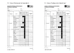
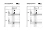
Страница 133: ...K65C K75C K95C K65C K75C K95C A 11 3 Muster Pr fhinweise f r Schaufellader A 11 3 Muster Pr fhinweise f r Schaufellader...

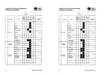
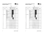
Страница 134: ...K65C K75C K95C K65C K75C K95C B B...

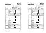
Страница 135: ...K65C K75C K95C K65C K75C K95C C C...

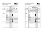
Страница 136: ...K65C K75C K95C K65C K75C K95C D D...

Страница 137: ...K65C K75C K95C K65C K75C K95C E E...

Страница 138: ...K65C K75C K95C K65C K75C K95C F F...

Отзывы: