


8
Setting up the Instrument
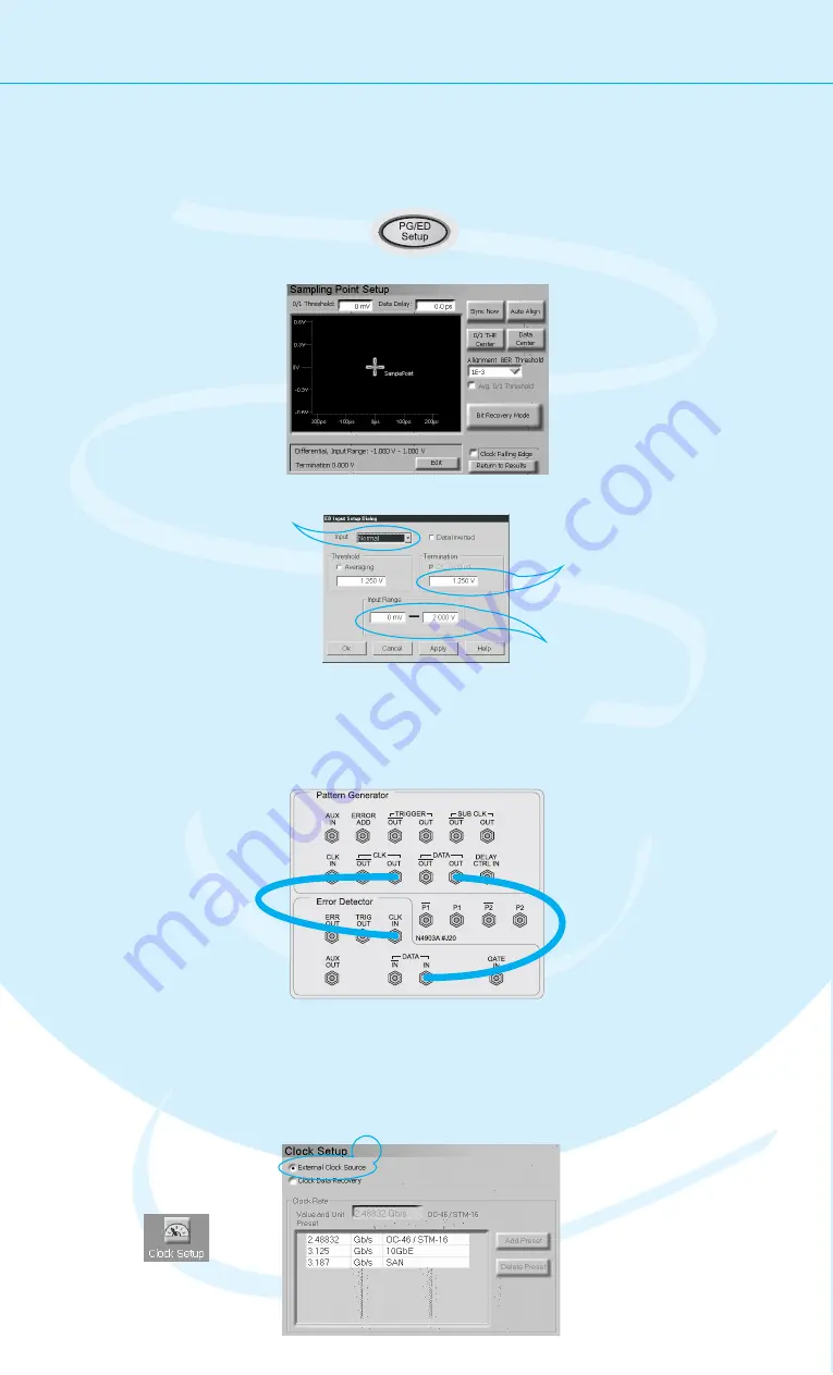
Setting up the Error Detector
The next step is to set up the error detector’s inputs.
Connecting the DUT
You can now connect the DUT. In our case you
just have to connect the following ports:
Defining the Clock
Switch to the
Clock Setup.
Select
as the source
for the clock signal.
External Clock
Source
1
2
We have to make sure that the error detector
uses the clock from the pattern generator:
2
PG Clock Out
PG Data Out
ED Data In
ED Clock In
Press the
button
twice to switch to the error
detector setup.
PG/ED Setup
Click the
button.
Edit
Set the Input to
.
This means, we need only one
cable that will be connected
between the pattern generator
and the data input port.
Normal
Enter the termination voltage
that matches the output
termination of the DUT, in our
case equal to the pattern
generator’s data output.
1
2
3
4
Set the
so that
it covers both the high and
low voltage levels of the
data signal.
Input Range
5


