


Setting Up the Instrument
7
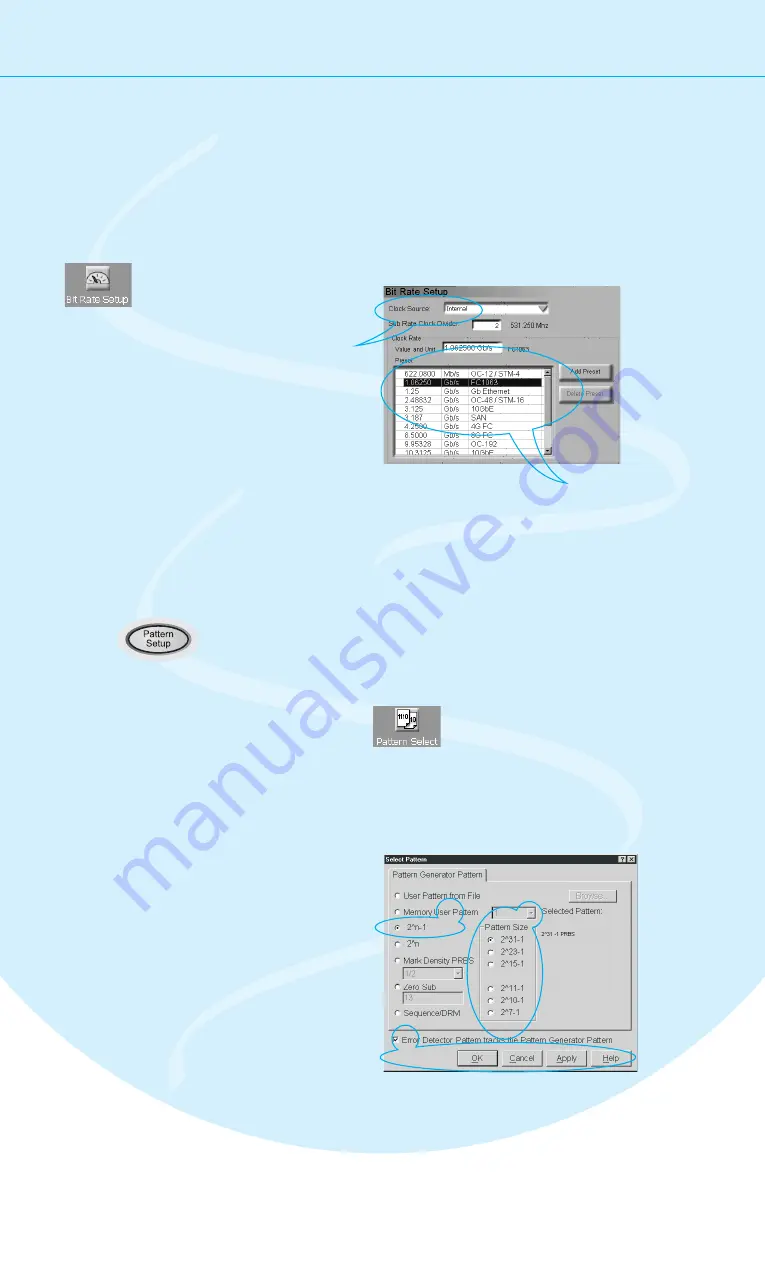
Set the Bit Rate
Now we want to set the pattern generator's bit rate. For now, we will use the
instrument's internal clock:
Switch to the
Bit Rate Setup.
Keep the Internal
Clock Source.
Select
from the list.
1.06250 Gb/s
Ethernet
You can easily add your
favorite frequencies to the list.
1
3
2
Now select the data pattern
to be used for the test:
Select the Pattern
Press the
button to switch to the
pattern editor.
Pattern Setup
Open the
dialog box.
Pattern
Select
Select the pattern
type 2^n-1 PRBS.
Select the pattern
size 2^31-1.
The cable does not convert any data.
Therefore, we use the same pattern
for the pattern generator and the
error detector.
Besides generated patterns like PRBS, you can also use memory-based
patterns. A large variety of useful test patterns is already provided, but
you can also set up your own custom patterns. See the Help for details.
1
2
3
4
5
3
5
4


