Agilent Technologies J-BERT N4903A Скачать руководство пользователя страница 9

Setting Up the Instrument

9

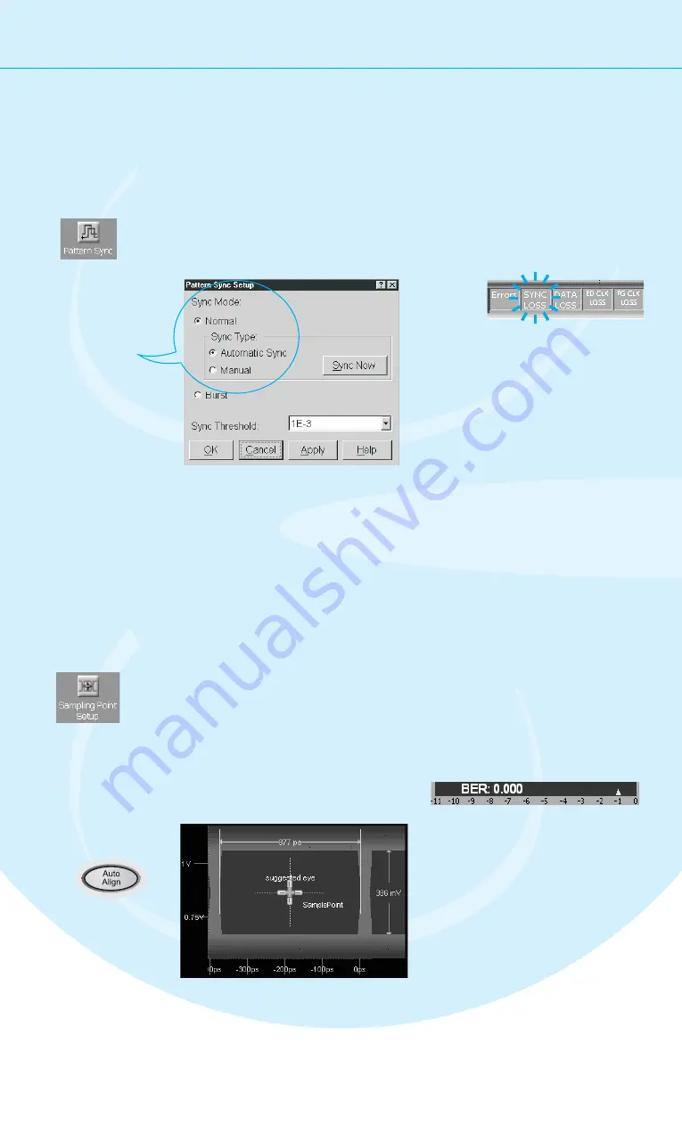
Synchronizing the Pattern

Now make sure that the error detector
automatically syncs to the data pattern:

With this setting, the error detector starts
synchronizing when the BER exceeds a
certain threshold value. You can see when
it has synchronized when the
indicator goes off.

Sync Loss

Setting the Sampling Point

Now set the optimum sampling point:

Open the

dialog box.

Pattern Sync

Setup

Make sure that

and
are selected.

Normal Sync Mode

Automatic Sync

1

2

Switch to the
Sampling Point Setup.

Press the

button

to measure the eye diagram
and to position the sampling
point at the center of the eye.

Auto Align

This usually takes
about 10 seconds.

The BER indicator in the top left
corner displays the current BER
at this sampling point which
should be 0 for this test.

1

2

If sync fails, the sampling point is

probably outside of the eye. You should proceed with

setting the sampling point anyway. As soon as the instrument

finds the eye, with the settings we just made, it will

automatically synchronize the patterns.

Содержание J-BERT N4903A

Страница 1: ...mation on the J BERT check out the Online Help The Help also offers printable versions of the User Guide and the Programming Guide You only need a few minutes to get started with the J BERT This Getti...

Страница 2: ...specified in the operation instructions All Light Emitting Diodes LEDs used in this product are Class 1 LEDs as per IEC 60825 1 Environmental Conditions Verify that all safety precautions are taken Th...

Страница 3: ...m any single phase AC power source supplying 100 240 V in the frequency range from 47 63 Hz The maximum power consumption is 450 VA with all options installed The power supply automatically adapts to...

Страница 4: ...PS 2 Mouse green Serial Port 1 Parallel Port VGA Monitor Ethernet Port 1 2 Audio Line Output Jack Audio Microphone Input Jack Diagnostic LED Stack USB 2 0 Channel 0 3 The Agilent J BERT is available i...

Страница 5: ...values by hand or the large knob to adjust values You can also use the knobs at the bottom of the instrument to change certain frequently used values in run time Navigating the GUI The menu buttons al...

Страница 6: ...tput Reset the instrument This sets all voltages and parameters to default values Now select the logic family LVDS for the data and clock port Check the values to make sure you can t damage your devic...

Страница 7: ...e used for the test Select the Pattern Press the button to switch to the pattern editor Pattern Setup Open the dialog box Pattern Select Select the pattern type 2 n 1 PRBS Select the pattern size 2 31...

Страница 8: ...etector uses the clock from the pattern generator 2 PG Clock Out PG Data Out ED Data In ED Clock In Press the button twice to switch to the error detector setup PG ED Setup Click the button Edit Set t...

Страница 9: ...e sure that and are selected Normal Sync Mode Automatic Sync 1 2 Switch to the Sampling Point Setup Press the button to measure the eye diagram and to position the sampling point at the center of the...

Страница 10: ...to move the sampling point horizontally Data In Delay You can see how the BER increases when measuring at the edge of the eye 1 2 Viewing Eye Results Now let s check the resulting eye Press the butto...

Страница 11: ...le be used for testing error correction algorithms Select because we do not need a measurement log file now No Logging Select a of 10 seconds as the measurement period Time 3 4 5 Press the button to s...

Страница 12: ...ument The software will automatically recognize the new component and provide the Interface Channel Icon and according setup functions in the window Jitter Perform the regular shutdown procedure provi...

Отзывы: