


7-12
Chapter 7
Service
Replacement Procedure
Cable/Probe Wand Replacement
Tools Required:
10 mm open-end wrench
9/16 inch open-end wrench
1/8 inch-wide flatblade screwdriver
Phillips No. 0 or posidrive screwdriver
Long-nose pliers
Special Tool:
Spanner/wrench (part number 85024-20041)
This special tool is pictured in
.
Refer to
.
1. Remove the nut with a 10 mm open-end wrench.
2. Remove the nose assembly and set aside.
CAUTION
The amplifier microcircuit is very sensitive to static electricity. Exercise full anti-static
precautions and use great care when performing the procedure.
Refer to
.
3. Remove the amplifier microcircuit. Remove the spring clip and elastic conductive strip. Place the
microcircuit in a static-safe place. It will be needed later in this procedure.
4. Remove the regulator housing covers by performing the procedure in
Regulator Housing Covers” on page 7-10
Refer to
.
5. Remove the connector body with the 9/16 inch wrench.
Refer to
.
6. Remove the four screws which hold in the regulator assembly. Desolder the colored wires attached to
the regulator assembly and remove the regulator assembly.
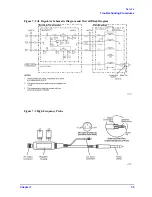
7. Remove the transition nut with the transition nut spanner (shown in
) and pull the inner
connector out of its keyed hole.
8. Unscrew the inner connector from the RF cable. Hold the nut with long nose pliers while turning the
connector.
9. Remove the hex nut with the special cable nut wrench (shown in
). The cable will now
come loose.
10. Insert the new cable into the regulator frame and attach the hex nut.
11. Make sure the insulator (shown in
) is inside the connector.
Содержание 85024A
Страница 4: ...iv ...
Страница 7: ...1 1 1 General Information ...
Страница 13: ...2 1 2 Accessories ...
Страница 19: ...3 1 3 Installation ...
Страница 24: ...3 6 Chapter3 Installation Returning the Product for Service ...
Страница 25: ...4 1 4 Operation ...
Страница 30: ...4 6 Chapter4 Operation Operator s Check ...
Страница 31: ...5 1 5 Performance Tests ...
Страница 40: ...5 10 Chapter5 Performance Tests Average Noise Level ...
Страница 41: ...6 1 6 Replaceable Parts ...
Страница 46: ...6 6 Chapter6 Replaceable Parts Parts Lists ...
Страница 47: ...7 1 7 Service ...
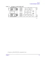
Страница 60: ...7 14 Chapter7 Service Replacement Procedure Figure 7 11 Regulator Parts and Wiring ...
Страница 64: ...7 18 Chapter7 Service Connector Inspection and Cleaning ...


