


7-8
Chapter 7
Service
Replacement Procedure
Replacement Procedure
Replacing the Probe Tip
Tools Required:
3/32 inch probe-tip nut driver (supplied with the probe)
10 mm open-end wrench
CAUTION
Use static precautions when performing the following procedures. The amplifier
microcircuit is very static sensitive and exposed during this procedure.
Refer to
.
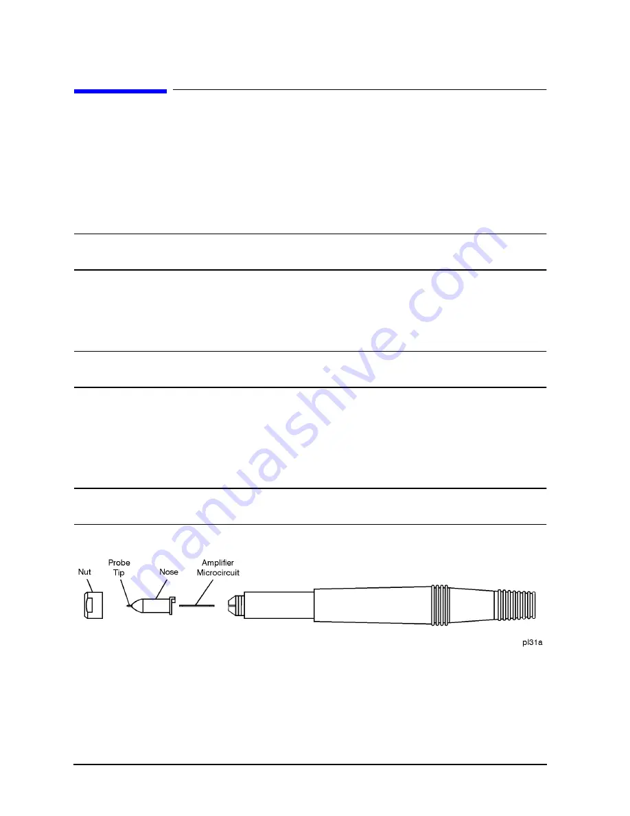
1. Remove the nut with a 10 mm open-end wrench.
2. Remove the nose assembly, leaving the microcircuit attached to the body of the probe.
CAUTION
Failure to remove the nose assembly prior to replacing the probe tip will result in damage
to the conductive elastomer on the new probe tip assembly.
3. Unscrew the damaged tip with the nut driver and discard the tip.
4. Screw in the new tip and lightly tighten it with a 3/32 inch nut driver.
(Overtightening the tip can damage the nose assembly.)
5. Install the nose assembly and nut. Tighten the nut with a 10 mm open-end wrench.
NOTE
The tip on the 10:1 divider can be replaced without disassembling the divider. Use the
3/32 inch probe tip driver.
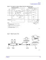
Figure 7-6
Probe End Disassembly
Содержание 85024A
Страница 4: ...iv ...
Страница 7: ...1 1 1 General Information ...
Страница 13: ...2 1 2 Accessories ...
Страница 19: ...3 1 3 Installation ...
Страница 24: ...3 6 Chapter3 Installation Returning the Product for Service ...
Страница 25: ...4 1 4 Operation ...
Страница 30: ...4 6 Chapter4 Operation Operator s Check ...
Страница 31: ...5 1 5 Performance Tests ...
Страница 40: ...5 10 Chapter5 Performance Tests Average Noise Level ...
Страница 41: ...6 1 6 Replaceable Parts ...
Страница 46: ...6 6 Chapter6 Replaceable Parts Parts Lists ...
Страница 47: ...7 1 7 Service ...
Страница 60: ...7 14 Chapter7 Service Replacement Procedure Figure 7 11 Regulator Parts and Wiring ...
Страница 64: ...7 18 Chapter7 Service Connector Inspection and Cleaning ...


