background image

Replacing Assemblies

6

16901A Logic Analysis System Service Guide

47


If the system is unplugged while it is off and then 
plugged back in, the system will not power on until the 
power button is pressed.

Using a Short Press of the Power Button

Pressing the power button on a frame for a short time (less 
than 2 seconds or so): 

Closes all programs that are running.

Writes all data to the disk.

Turns off the power supply.

If the power button is depressed for a short time (less than 
2 seconds or so) while another instrument has an open 
Remote Desktop connection to this instrument, a message on 
the logic analyzer screen (not on the remote desktop) will 
pop up asking if you really want to power down. Clicking 
the 'yes' button results in the above events. Clicking 'no' will 
prevent the shutdown and not answering the dialog box 
(neither clicking "Yes" or "No") will have no effect. Further 
short presses on the power button will have no effect.

Using a Long Press of the Power Button

Pressing the power button for more than 4 seconds will 
power the system down abruptly. Use this method only when 
other methods have not responded:

Programs that are running will not be shut down. Any 
data that has not been written to the disk will be lost.

Turns off the power supply.

If the system is unplugged while it is off and then 
plugged back in, the system will not power on until the 
power button is pressed.

If the system does not boot, the hard disk drive will need 
to be re- imaged.

Unplugging the Power Cord or Power Loss

Unplugging power while the instrument is turned on or a 
power loss is similar to the long press of the power button 
with one exception:

When the system is plugged back in, it will power up and 
boot into Windows.

Содержание 16901A

Страница 1: ...Agilent Technologies Agilent 16901A Logic Analysis System Service Guide...

Страница 2: ...such license Restricted Rights Legend If software is for use in the performance of a U S Government prime contract or sub contract Software is delivered and licensed as Commercial computer soft ware a...

Страница 3: ...6902A frames Built in 15 inch TFT color touch screen LCD display 1 024 x 768 XGA resolution 250 GB hard disk drive or external hard drive 16901A Option 109 10 100 Base T LAN port USB 2 0 ports six tot...

Страница 4: ...nt of defective assemblies This service guide contains information for finding a defective assembly by testing and servicing the 16901A logic analysis system This instrument can be returned to Agilent...

Страница 5: ...for troubleshooting the instrument Chapter 6 Replacing Assemblies tells how to replace the instrument and assemblies of the instrument and how to return them to Agilent Technologies Chapter 7 Replace...

Страница 6: ...6 16901A Logic Analysis System Service Guide...

Страница 7: ...y power 16 To connect multiple frames 17 To install measurement modules 17 To clean the instrument 17 3 Testing Performance Self Tests 20 Test Interval 20 To perform the power up tests 21 4 Calibratin...

Страница 8: ...power supply 51 Secondary power supply 52 To remove and replace the PCI or display board 54 To remove and replace the motherboard 55 To remove and replace the front panel assembly 57 To remove and re...

Страница 9: ...Parts Ordering Replaceable Parts 76 Exchange Assemblies 76 Power Cables and Plug Configurations 77 Replaceable Parts List 79 Cover and Front Panel Assemblies 80 16901A Frame 83 8 Theory of Operation...

Страница 10: ...10 16901A Logic Analysis System Service Guide Contents...

Страница 11: ...ormation Electrical and Operating Environment Characteristics 12 Dimensions 14 This chapter contains information on electrical and operating environment characteristics and dimensions See the logic an...

Страница 12: ...000 m 10 000 ft Humidity Relative humidity 8 to 80 at 40 C 104 F Avoid sudden extreme temperature changes which could cause condensation on the circuit board Vibration Operating random vibration 0 500...

Страница 13: ...nformation 1 16901A Logic Analysis System Service Guide 13 Trigger In The Trigger In connector is 5V Max pk and DC CAT I line isolated Clock In The Clock In connector is 5 5V Max pk and DC CAT I line...

Страница 14: ...14 16901A Logic Analysis System Service Guide 1 General Information Dimensions The following figure provides dimensions for the 16901A logic analysis system mainframe in centimeters and inches...

Страница 15: ...c Analysis System Service Guide Agilent Technologies 2 Preparing for Use To inspect the logic analysis system 16 To apply power 16 To connect multiple frames 17 To install measurement modules 17 To cl...

Страница 16: ...ting for a claim settlement Contact information is located on page 4 To apply power 1 Connect the supplied power cord to the instrument and to the power source This instrument autodetects the line vol...

Страница 17: ...ww agilent com Search for 16901A Logic Analysis System Look under Technical Support and then Manuals and Guides To install measurement modules For general information on installing a measurement modul...

Страница 18: ...18 16901A Logic Analysis System Service Guide 2 Preparing for Use...

Страница 19: ...erform the power up tests 21 To ensure the logic analysis system is operating correctly you can perform software tests self tests on the system Directions for performing the software tests are given i...

Страница 20: ...lect on the screen For descriptions of the tests refer to Chapter 8 Theory of Operation Perform the self tests as an acceptance test when receiving the logic analysis system or when the logic analysis...

Страница 21: ...ts A keyboard and mouse must be connected to the mainframe to observe the results of the power up tests 1 Exit all logic analysis sessions 2 Press the power switch for about 1 second and release wait...

Страница 22: ...22 16901A Logic Analysis System Service Guide 3 Testing Performance...

Страница 23: ...23 Agilent 16901A Logic Analysis System Service Guide Agilent Technologies 4 Calibrating and Adjusting Calibration Strategy 24 Calibrations and Adjustments for Modules 24...

Страница 24: ...em does not require operational accuracy calibration Calibrations and Adjustments for Modules The individual modules that plug into the 16901A logic analysis system mainframe may require calibration o...

Страница 25: ...onent level repair If you suspect a problem start at the top of the first flowchart During the troubleshooting instructions the flowcharts will direct you to perform other tests The other tests are lo...

Страница 26: ...te defective assemblies The flowcharts refer to other tests to help isolate the trouble The circled references on the charts indicate connections with the other flowcharts or other parts within the sa...

Страница 27: ...ing to windows login Start Attach keyboard mouse and power cord Remove all user installed PCI cards see To remove replace optional interface cards in chapter 7 Apply power Does the logic analyzer appl...

Страница 28: ...l is asserted from CPU or MIB module interface board Check the CPU to MIB cables Check the AUX 5V power Go to To troubleshoot power problems in this chapter Replace the CPU Replace the MIB Check for a...

Страница 29: ...ndows and check display settings Set the default to display 1 internal display at 1024x768 pixels 16 bit color depth Check all cables to the front panel assembly Check all cables to the CPU motherboar...

Страница 30: ...nce and is the power LED steady on Yes Does the instrument reach 7 in the boot sequence Yes Enter BIOS setup and reset to default Failed OS boot from hard drive Replace the CPU motherboard Check the h...

Страница 31: ...Flowchart 5 Reinstall the logic analyzer application Replace the MIB board Replace the PCI bridge board Check all cables to front panel assembly Check all cables to CPU motherboard Check all cables t...

Страница 32: ...eck the power supply voltages 1 Turn off the instrument using one of the methods descirbed in To power off the system on page 46 2 Disconnect the instrument s power cord move the instrument to a stati...

Страница 33: ...ystem Service Guide 33 7 Referring to the graphics that follow note problems with the power supply then return to Figure 2 16901A Power Troubleshooting Flowchart on page 28 Power Supply Test Points 5...

Страница 34: ...DC Converter U56 on MIB MIB PCI Board Power MAX Power 3 3V 4A 5V 1A 5V AUX 0 5A Acquisition Slot A MAX Power 3 3V 10 8A 5V 5A 12V 0 5A 12V 0 5A 3 25V 3A 5 2V 5 6A Acquisition Slot B MAX Power 3 3V 10...

Страница 35: ...functional operation of the logic analyzer Perform the self tests as an acceptance test when receiving the logic analyzer or when the logic analyzer is repaired 1 In the Agilent Logic Analyzer applic...

Страница 36: ...36 16901A Logic Analysis System Service Guide 5 Troubleshooting To exit the test system 1 Simply close the self test dialog No additional actions are required...

Страница 37: ...keyboard mouse and external USB DVD reader connected On a 16901A Series Logic Analysis system with Windows 7 Installation The 16901A series of Logic Analysis systems with serial number of MY51420101...

Страница 38: ...ystem with the Windows 7 operating system This is the normal startup of the system Agilent Recovery System You should select this option when you want to restore repair your Logic Analysis system soft...

Страница 39: ...with options to choose You can enter 1 to run Check Disk on the Logic Analysis system s hard disk drive If the recovery process encounters any problems while running Check Disk it reports these proble...

Страница 40: ...ting that the recovery process overwrites the data on C drive If you want to save your data to a CD or to another machine before you proceed further then exit the recovery process and save your data E...

Страница 41: ...ing Agilent Service Support To locate a sales or service office near you go to http www agilent com find contactus NOTE There are situations when you are not able to run the recovery process for insta...

Страница 42: ...42 16901A Logic Analysis System Service Guide 5 Troubleshooting...

Страница 43: ...the motherboard 55 To remove and replace the front panel assembly 57 To remove and replace the backlight inverter board 59 To remove and replace the touch screen controller board 61 To remove and rep...

Страница 44: ...drivers 1 Pozi drive screwdriver 13 16 inch deep well nut driver 5 mm nut driver 1 4 inch hollow shaft nut driver WARNING Hazardous voltages exist on the power supply To avoid electrical shock disconn...

Страница 45: ...Logic Analyzer application s install directory For example the default location is C Program Files Agilent Technologies Logic Analyzer License Floating license files are located in the License Files...

Страница 46: ...llowing Closes all programs that are running Writes all data to the disk Turns off the power supply WARNING Hazardous voltages exist on the power supply To avoid electrical shock disconnect power from...

Страница 47: ...g no will prevent the shutdown and not answering the dialog box neither clicking Yes or No will have no effect Further short presses on the power button will have no effect Using a Long Press of the P...

Страница 48: ...be connected together in multi card Master Expander modules unless stated otherwise See also the service guide that came with your measurement module 1 Perform previous procedures To prepare the inst...

Страница 49: ...thumb screws until finger tight in the same order used in step 5 above If using a hex socket or torque driver avoid over tightening 2 in lb maximum 8 For correct air circulation install filler panels...

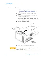
Страница 50: ...move 6 screws that secure the cover to the chassis Optional Removing the shroud may make it easier to remove and replace the cover In this case remove 4 T10 screws then remove the shroud 4 Slide the c...

Страница 51: ...des of the connector to disconnect the top 600 watt power supply cable from the module interface board MIB 3 Press the single release tab to disconnect the lower 600 watt power supply cable from the M...

Страница 52: ...condary power supply The secondary power supply is 175 watts and may look different than the one shown here 1 Perform the procedures To prepare the instrument for disassembly on page 46 To remove and...

Страница 53: ...y cable press release tab 4 Using a Torx T10 screwdriver remove the 2 screws that secure the secondary power supply to the tray 5 Snap the power supply off the tray assembly see enlargement of snap in...

Страница 54: ...ge 50 2 Disconnect the cable from the board you are replacing 3 Using a Torx T10 screwdriver remove the screws securing the board to the rear panel 4 Lift the board out of the socket to remove 5 To re...

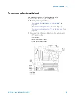
Страница 55: ...ent 1 Perform previous procedures To prepare the instrument for disassembly on page 46 To remove and replace the cover on page 50 To remove and replace the PCI or display board on page 54 2 Disconnect...

Страница 56: ...3 Using a 5 mm hex nut driver remove the 6 Hex Studs securing the connectors to the rear panel 4 Using a Torx T10 screwdriver remove the 8 screws that secure the motherboard to the deck 5 Reverse this...

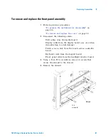
Страница 57: ...on page 50 2 Disconnect the following cables USB cables from the motherboard Display cable from the display board use care when disconnecting to avoid damage Touch screen cable from the touch screen c...

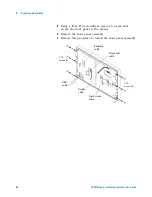
Страница 58: ...Torx T10 screwdriver remove 6 screws that secure the front panel to the chassis 6 Remove the front panel assembly 7 Reverse this procedure to install the front panel assembly T 10 screws 3 USB cables...

Страница 59: ...rter board 1 Perform previous procedures To prepare the instrument for disassembly on page 46 To remove and replace the cover on page 50 To remove and replace the front panel assembly on page 57 2 Usi...

Страница 60: ...nect the backlight cables from the inverter board 4 Using a Torx T6 screwdriver remove the 2 screws securing the board to the front panel 5 Remove the board 6 Reverse this procedure to install the bac...

Страница 61: ...6 To remove and replace the cover on page 50 To remove and replace the front panel assembly on page 57 2 Disconnect the touch screen cable from the touch screen controller board 3 Using a Torx T10 scr...

Страница 62: ...lace the front panel assembly on page 57 2 Using a Torx T10 screwdriver remove the 2 screws securing the touch screen controller board to the front panel bracket assembly 3 Using a Torx T10 screwdrive...

Страница 63: ...page 46 To remove and replace the cover on page 50 To remove and replace the front panel assembly on page 57 To remove and replace the front panel bracket assembly on page 62 2 Using a Torx T10 screw...

Страница 64: ...ove and replace the front panel bracket assembly on page 62 2 Using a Torx T10 screwdriver remove the 2 screws securing the display assembly to the front panel bracket assembly 3 Remove the alignment...

Страница 65: ...lacing Assemblies 6 16901A Logic Analysis System Service Guide 65 4 Gently pry the touch screen from the LCD It is held on with double sided tape 5 Reverse this procedure to replace the display assemb...

Страница 66: ...ll to remove the cursor knob from the front of the frame 3 Using a Torx T10 screwdriver remove the 3 screws securing the keypad board to the front frame 4 Remove the keypad board and keypad from the f...

Страница 67: ...Replacing Assemblies 6 16901A Logic Analysis System Service Guide 67 5 Reverse this procedure to install the keypad and keypad board Note the alignment pins on the frame and the holes in the board...

Страница 68: ...installed Therefore once you get back your logic analyzer with the replaced hard disk you need to first restore your system software see To restore the system software on page 37 then install the Logi...

Страница 69: ...eplace the front panel assembly on page 57 2 Using a Torx T10 screwdriver remove the 2 side screws securing the tray assembly to the chassis 3 Slide the tray assembly out far enough to disconnect the...

Страница 70: ...s To prepare the instrument for disassembly on page 46 To remove and replace the cover on page 50 2 Disconnect the fan cable from the module interface board MIB 3 Using a Torx T25 screwdriver remove t...

Страница 71: ...assembly on page 69 2 Using a Torx T10 screwdriver remove the 4 screws securing the baffle to the chassis 3 Disconnect the fan cable for the fan you are replacing from the fan cable assembly If repla...

Страница 72: ...nect the line filter assembly cables from the power supplies In order to press the release latches on the lower cable connection you may need to slide the tray assembly part way out following the proc...

Страница 73: ...le interface board of your 16901A logic analysis system you send your logic analysis unit to Agilent for repair replacement of the module interface board See Returning Assemblies on page 74 to know mo...

Страница 74: ...the part to be returned Name and address of owner Model number Serial number Description of service required or failure indications 2 Remove accessories from the logic analyzer Only return accessorie...

Страница 75: ...gilent Technologies 7 Replaceable Parts Ordering Replaceable Parts 76 Power Cables and Plug Configurations 77 Replaceable Parts List 79 This chapter contains information for identifying and ordering r...

Страница 76: ...at has been repaired and performance verified by Agilent Technologies After you receive the exchange assembly return the defective assembly to Agilent Technologies A United States customer has 30 days...

Страница 77: ...r Cables and Plug Configurations Plug Type male connector Agilent Part No Plug Orientation female connector Cable Length Cable Color Country Option 900 250V 8120 1703 IEC 320 1 C13 90 2 3 meters Mint...

Страница 78: ...EC 320 1 C13 90 2 0 meters Flint Gray Israel Option 920 250V 8121 6871 IEC 320 1 C13 90 2 0 meters Flink Gray Argentina Option 921 8120 6979 IIEC 60320 1 C13 90 4 5 meters Flint Gray Chile Option 922...

Страница 79: ...reference designation The exploded views do not show all of the parts in the replaceable parts lists Information included for each part in the list consists of the following Reference designator A As...

Страница 80: ...6901A Logic Analysis System Service Guide 7 Replaceable Parts Cover and Front Panel Assemblies The 16901A logic analysis system has a built in touch screen color display and also support external disp...

Страница 81: ...80 68702 1 Accessory pouch MP2 16800 01201 1 Bracket front panel MP4 16901 04101 1 Cover MP5 54810 61001 4 Foot bottom MP6 16800 40503 4 Foot side MP7 16800 40201 1 Front frame MP8 16600 68707 1 Handl...

Страница 82: ...not shown W2 16800 61603 1 Front panel cable not shown W3 16800 61614 1 Inverter cable not shown W4 D8104 61604 1 Touch screen cable W5 16800 61611 1 USB dual cable Table 3 Replaceable parts for the c...

Страница 83: ...Replaceable Parts 7 16901A Logic Analysis System Service Guide 83 16901A Frame The 16901A logic analysis system is modular with slots for two measurement modules...

Страница 84: ...th CPU and SDRAM MP30 1150 7913 1 Mouse optical wheel not shown MP31 16903 66404 1 PCI card MP32 16800 01205 1 PCI card bracket MP33 16903 66504 1 PCI card w bracket assembly MP34 0950 4812 1 Power su...

Страница 85: ...wing table the old part numbers specified in Table 4 are applicable W6 16800 61609 1 Cable CPU power W7 16800 61608 1 Cable fan assembly W8 16800 61601 1 Cable front panel W9 16800 61610 1 Cable hard...

Страница 86: ...iption MP29 0960 2939 No Motherboard W10 16901 61607 No Motherboard Switch Cable W6 16800 61617 Yes Cable CPU power MP18 16800 00202 No CPU IO Panel MP29 16901 68712 No Motherboard Assembly 16901 0010...

Страница 87: ...ory of Operation Block Level Theory 88 This chapter describes the theory of operation for the 16901A logic analysis system The information in this chapter is to help you understand how the logic analy...

Страница 88: ...age 91 Disk drives more on page 91 Power supply more on page 92 Hard Disk Drive SATA Bus Power CPU Motherboard PCI Express x16 15 Touch Screen Grid Option 103 Keypad Board 15 Flat Panel LCD Display Fr...

Страница 89: ...e MIB subsystem block diagram shown here includes Module bus FPGA s more on page 93 I O FPGA more on page 93 Supported rear panel signals include Multiframe Input Output more on page 93 Trigger IN OUT...

Страница 90: ...Connector s 1 or 2 Fan Control PLD Rear Panel Signals PCI Board Connector Fan Connectors Power Connectors 3 CPU Power Connector CPU Power Switch Connector Power Switch Connector Power Sense Connector...

Страница 91: ...eed grade will vary over the life of the product Standard I Os built into the ATX board are PS 2 serial port parallel port USB 2 0 10 100 Mbit LAN and VGA Video One PCI slot and one PCI Express x1 slo...

Страница 92: ...e drops below about 90 of regulation Power down can also be caused by an over temperature sense circuit In this case the PLD notifies the CPU the user receives a warning window and a soft power down i...

Страница 93: ...PGA component is system correlation time alignment of the measurement modules and possible other modules connected through the multiframe port or Trigger In connector This is done with eight 52 bit co...

Страница 94: ...s complicated by the need to handle variable threshold levels The circuit consists of a programmable 12 bit DAC and comparator This combined with a level shift and divide circuit allows for a 5 V inpu...

Страница 95: ...en from a DC DC boost converter circuit This circuit creates a linear voltage ramp from 12 V to 24 V across the operating temperature range The purpose of this circuit is to increase air flow as neede...

Страница 96: ...he touch screen controller board is a 3M SC801U Mounted in front of the flat panel display is a touch screen grid connected directly to the touch screen controller The controller interprets touch pres...

Страница 97: ...pter LCD or external VGA was displaying the Windows desktop when the system was last shut down It is possible to get a blank screen In this situation you can press and hold the Touch Off button on the...

Страница 98: ...provide system services They run before any user has logged onto the system If the logic analyzer product is installed on the system a logic analyzer service called Agilent Logic Analysis should be ru...

Страница 99: ...e started older software revisions If the drivers are not loaded the GUI application will start in offline mode Once the GUI application is running the user can go online with local hardware or the ha...

Страница 100: ...tem level recovery This recovery mechanism is used to fix system level problems including damage done by viruses or previously installed software problems with operating system bugchecks blue screen e...

Страница 101: ...est All self tests are consolidated into a single self test dialog The self test dialog contains a pane which allows the user to select the test suite and a pane which allows the user to select a spec...

Страница 102: ...102 16901A Logic Analysis System Service Guide 8 Theory of Operation...

Страница 103: ...play 3 display assembly removal 64 display card removal 54 E exchange assemblies 76 exploded view cover 80 frame 83 front panel 80 F fan removal 70 features 3 flowcharts troubleshooting 26 frame repla...

Страница 104: ...icense file 45 self tests 35 service contacting Agilent 41 service office 4 shipping damage 16 shipping requirements 12 shut down 46 specifications see characteristics 12 storage requirements 12 Syste...

Отзывы: