147
Using the Oscilloscope
The Scope Auto Measure Menu
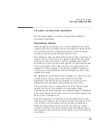
Automatic measurement algorithms
The following explains top and base voltages, then defines the
measurement algorithms.
Top and base voltages
All measurements except Vp_p are calculated using the Vtop (100%
voltage) and Vbase (0% voltage) levels of the displayed waveform. The
Vtop and Vbase levels are determined from an occurrence density
histogram of the data points displayed on the screen.
The digitizing oscilloscope displays 8-bit vertical voltage resolution. In
other words, the vertical axis of the display is divided into 28 voltage
levels. Each of these 256 levels is called a quantization level. Each
waveform has at least 500 data points displayed on the horizontal axis
of the screen. Each of these data points has one quantization level
assigned to it. The histogram is calculated by adding the number of
occurrences of each quantization level of all displayed points on the
displayed waveform.
The quantization level with the greatest number of occurrences in the
top half of the waveform corresponds to the Vtop level. The
quantization level with the greatest number of occurrences in the
bottom half of the waveform corresponds to the Vbase level.
If Vtop and Vbase do not contain at least 5% of the 500 data points
displayed on screen, Vtop defaults to the maximum voltage
(Vmaximum) and Vbase defaults to the minimum voltage (Vminimum)
found on the display. An example of this case would be measurements
made on sine or triangle waves.
From this information, the instrument can determine the 10%, 50%,
and 90% points, which are used in most automatic measurements. The
Vtop or Vbase of the waveform is not necessarily the maximum or
minimum voltage present on the waveform. If a pulse has a slight
amount of overshoot, it would be wrong to select the highest peak of
the waveform as the top because the waveform proper rests below the
perturbation.
Содержание 1670E Series
Страница 6: ...6 In This Book...
Страница 26: ...26 Contents...
Страница 27: ...27 Section 1 Logic Analyzer...
Страница 28: ...28...
Страница 29: ...29 1 Logic Analyzer Overview...
Страница 39: ...39 2 Connecting Peripherals...
Страница 49: ...49 3 Using the Logic Analyzer...
Страница 72: ...72 Using the Logic Analyzer The Inverse Assembler...
Страница 73: ...73 4 Using the Trigger Menu...
Страница 101: ...101 5 Using the Oscilloscope...
Страница 151: ...151 6 Using the Pattern Generator...
Страница 199: ...199 7 Triggering Examples...
Страница 237: ...237 8 File Management...
Страница 249: ...249 9 Logic Analyzer Reference...
Страница 360: ...360 Logic Analyzer Reference The Compare Menu...
Страница 361: ...361 10 System Performance Analysis SPA Software...
Страница 397: ...397 11 Logic Analyzer Concepts...
Страница 422: ...422 Logic Analyzer Concepts The Analyzer Hardware HP 1660E ES EP series analyzer theory HP 1660EP logic analyzer board...
Страница 426: ...426 Logic Analyzer Concepts The Analyzer Hardware Logic acquisition board theory Logic acquisition board...
Страница 430: ...430 Logic Analyzer Concepts The Analyzer Hardware Oscilloscope board theory Oscilloscope board...
Страница 439: ...439 12 Troubleshooting the Logic Analyzer...
Страница 455: ...455 13 Specifications...
Страница 471: ...471 14 Operator s Service...
Страница 479: ...479 Operator s Service Troubleshooting Troubleshooting Flowchart 2...
Страница 491: ...491 Section 2 LAN...
Страница 492: ...492...
Страница 493: ...493 15 Introducing the LAN Interface...
Страница 497: ...497 16 Connecting and Configuring the LAN...
Страница 506: ...506 Connecting and Configuring the LAN Connecting and Configuring the LAN...
Страница 507: ...507 17 Accessing the Logic Analyzer File System Using the LAN...
Страница 515: ...515 18 Using the LAN s X Window Interface...
Страница 527: ...527 19 Retrieving and Restoring Data Using the LAN...
Страница 539: ...539 20 Programming the Logic Analyzer Using the LAN...
Страница 546: ...546 Programming the Logic Analyzer Using the LAN Programming the Logic Analyzer Using the LAN...
Страница 547: ...547 21 LAN Concepts...
Страница 555: ...555 22 Troubleshooting the LAN Connection...
Страница 580: ...580 Troubleshooting the LAN Connection Getting Service Support...
Страница 581: ...581 Section 3 Symbol Utility...
Страница 582: ...582...
Страница 583: ...583 23 Symbol Utility Introduction...
Страница 588: ...588 Symbol Utility Introduction Symbol Utility Introduction...
Страница 589: ...589 24 Getting Started with the Symbol Utility...
Страница 597: ...597 25 Using the Symbol Utility...
Страница 609: ...609 26 Symbol Utility Features and Functions...

