background image

c

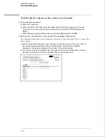
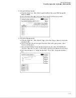
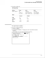
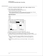
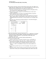
Adjust the pulse generator channel 1 Delay, then select Precision Edge Find in the
oscilloscope Delta T menu.  Repeat this step until the pulses are aligned according to
the setup time of the setup/hold combination selected, +0.0 ps or 

100 ps.

4

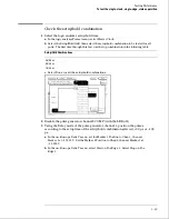
Select the clock to be tested.

a

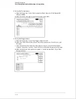
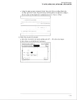
In the Master Clock menu, select the clock field to be tested, then select the clock
edge as indicated in the table.  The first time through this test, use the top clock and
edge in the following table.

Clocks

J

K

b

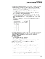
Connect the clock to be tested to the pulse generator channel 2 output.

c

Select Done to exit the Master Clock menu.

Testing Performance

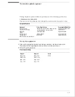
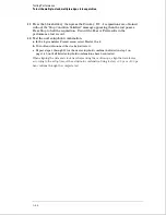
To test the single-clock, single-edge, state acquisition

3–30

Содержание 1664A

Страница 1: ...4 97005 Second edition January 2000 For Safety information Warranties and Regulatory information see the pages at the end of the book Copyright Agilent Technologies 1987 2000 All Rights Reserved Agile...

Страница 2: ...ytes in half channel mode Marker measurements 12 levels of trigger sequencing for state and 10 levels of sequential triggering for timing 100 MHz time and number of states tagging Full programmability...

Страница 3: ...The Agilent Technologies 1664A Logic Analyzer iii...

Страница 4: ...Chapter 3 gives instructions on how to test the performance of the logic analyzer Chapter 4 contains calibration instructions for the logic analyzer Chapter 5 contains self tests and flowcharts for tr...

Страница 5: ...eshold accuracy 3 8 Set up the equipment 3 8 Set up the logic analyzer 3 9 Connect the logic analyzer 3 9 Test the TTL threshold 3 10 Test the ECL threshold 3 12 Test the User threshold 3 13 Test the...

Страница 6: ...the data 1 58 Performance Test Record 3 59 4 Calibrating and Adjusting Logic analyzer calibration 4 2 Set up the equipment 4 2 To adjust the CRT monitor alignment 4 3 To adjust the CRT intensity 4 5...

Страница 7: ...he fan 6 12 To remove and replace the line filter 6 12 To remove and replace the optional GPIB and RS 232C cables 6 13 To return assemblies 6 14 7 Replaceable Parts Replaceable Parts Ordering 7 2 Expl...

Страница 8: ...Contents viii...

Страница 9: ...1 Accessories 1 2 Specifications 1 3 Characteristics 1 3 Supplemental Characteristics 1 4 Recommended Test Equipment 1 8 General Information...

Страница 10: ...Probe ground 5 per pack 5959 9334 2 User s Reference 01660 90904 1 Accessories Pouch 01660 84501 1 HIL Mouse A2838A 1 Accessories Available Other accessories available for the 1664A Logic Analyzer ar...

Страница 11: ...4 0 0 0 ns adjustable in 500 ps increments Multiple Clocks Multiple Edges 0 0 4 5 ns through 4 5 0 0 ns adjustable in 500 ps increments Specified for an input signal VH 0 9 V VL 1 7 V slew rate 1 V ns...

Страница 12: ...e Interval Accuracy sample period channel to channel skew 0 01 time reading Triggering Sequencer Speed 125 MHz maximum State Sequence Levels 12 Timing Sequence Levels 10 Maximum Occurrence Counter Val...

Страница 13: ...ided in the Configuration and Format menus for identifying high low or changing states on the inputs Markers Two markers X and O are shown as vertical dashed lines on the display Trigger Displayed as...

Страница 14: ...atterns must be specified for both markers and statistics are kept only when both patterns can be found in an acquisition Statistics are minimum X to O time maximum X to O time average X to O time and...

Страница 15: ...Class A equipment SABS RAA Act No 24 1990 Immunity EN50082 1 Code1 Notes2 IEC 801 2 ESD 4kV CD 8kV AD 2 IEC 801 3 Rad 3V m 1 IEC 801 4 EFT 1kV 2 1 Performance Codes 1 PASS Normal operations no effect...

Страница 16: ...48 inch 2GHz bandwidth Agilent 8120 1840 P T SMA Coax Cable Qty 3 18 GHz bandwidth Agilent 8120 4948 P Adapter Qty 4 SMA m BNC f Agilent 1250 1200 P T Adapter SMA f BNC m Agilent 1250 2015 P Coupler...

Страница 17: ...gic analyzer 2 2 Ferrites 2 3 To apply power 2 4 To operate the user interface 2 4 To set the line voltage 2 4 To degauss the display 2 5 To clean the logic analyzer 2 5 To test the logic analyzer 2 5...

Страница 18: ...re or ship the logic analyzer in environments within the following limits Temperature 40 C to 75 C Humidity Up to 90 at 65 C Altitude Up to 15 300 meters 50 000 feet Protect the logic analyzer from te...

Страница 19: ...rrite will not affect the normal operation of the analyzer Ferrite Installation Instructions Use the following steps to install the ferrite on the logic analyzer cable 1 Place the ferrite halves and s...

Страница 20: ...aceable Parts for option numbers of available power cables and plug configurations 3 Turn on the instrument power switch located on the front panel To operate the user interface To select a field on t...

Страница 21: ...the CRT might become magnetized and display data might become distorted To correct this condition degauss the CRT with a conventional external television type degaussing coil To clean the logic analy...

Страница 22: ...2 6...

Страница 23: ...est the glitch capture 3 17 To test the single clock single edge state acquisition 3 23 To test the multiple clock multiple edge state acquisition 3 34 To test the single clock multiple edge state acq...

Страница 24: ...examples in this chapter were performed using an 1664A The performance verification procedures starting on page 3 8 are each shown from power up To exactly duplicate the set ups in the tests save the...

Страница 25: ...ey Load the disk containing the performance verification self tests into the disk drive normally the same as the boot disk 4 Select the box labeled Continue and press the Select key 5 After the test f...

Страница 26: ...ws how to run all tests at once When the tests finish the status for each test shows Passed or Failed and the status for the All System Tests changes from Untested to Tested Note that the Front Panel...

Страница 27: ...and the screen changes to half bright c Select Continue and the test screen shows the Display Test status changed to Tested 12 Record the results of the tests on the performance test record at the end...

Страница 28: ...tions of Berg strip a Solder a jumper wire to all pins on one side of the Berg strip b Solder a jumper wire to all pins on the other side of the Berg strip c Solder two resistors to the Berg strip one...

Страница 29: ...de of the Berg strip b Solder a jumper wire to all pins on the other side of the Berg strip c Solder the center of the BNC connector to the center pin of one row on the Berg strip d Solder the ground...

Страница 30: ...the limits listed on the performance test record Equipment Required Equipment Critical Specifications Recommended Model Part Digital Multimeter 0 1 mV resolution 0 005 accuracy Agilent 3458A Function...

Страница 31: ...eld Select Timing in the pop up menu Connect the logic analyzer 1 Using the 17 by 2 test connector BNC cable and probe tip assembly connect the data and clock channels of pod 1 to one side of the BNC...

Страница 32: ...fy the voltage The activity indicators for pod 1 should show all data channels and the J clock channel at a logic high 3 Using the Modify down arrow on the function generator decrease offset voltage i...

Страница 33: ...rator increase offset voltage in 1 mV increments until all activity indicators for pod 1 show the channels at a logic high Record the function generator voltage in the performance test record Testing...

Страница 34: ...fy down arrow on the function generator decrease offset voltage in 1 mV increments until all activity indicators for pod 1 show the channels are at a logic low Record the function generator voltage in...

Страница 35: ...lock channel at a logic high 3 Using the Modify down arrow on the function generator decrease offset voltage in 1 mV increments until all activity indicators for pod 1 show the channels at a logic low...

Страница 36: ...channel at a logic high 3 Using the Modify down arrow on the function generator decrease offset voltage in 1 mV increments until all activity indicators for pod 1 show the channels at a logic low Reco...

Страница 37: ...ing the Modify down arrow on the function generator decrease offset voltage in 1 mV increments until all activity indicators for pod 1 show the channels at a logic low Record the function generator vo...

Страница 38: ...ector and probe tip assembly connect the data and clock channels of pod 2 to the output of the function generator 2 Start with Test the TTL threshold on page 3 10 substituting pod 2 for pod 1 Testing...

Страница 39: ...igitizing Oscilloscope 6 GHz bandwidth 58 ps rise time Agilent 54121T SMA Coax Qty 3 18 GHz bandwidth Agilent 8120 4948 Adapter Qty 4 SMA m BNC f Agilent 1250 1200 Coupler Qty 4 BNC m m Agilent 1250 0...

Страница 40: ...Config key Assign all pod fields to Machine 1 To assign the pod fields select the pod fields then select Machine 1 in the pop up menu 2 In the Analyzer 1 box select the Type field Select Timing in th...

Страница 41: ...put To 8131A Channel 1 Output To 8131A Channel 2 Output To 8131A Channel 2 Output 1 Pod 1 ch 0 2 4 6 J clock Pod 1 ch 1 3 5 7 Pod 1 ch 8 10 12 14 Pod 1 ch 9 11 13 15 2 Pod 2 ch 0 2 4 6 K clock Pod 2 c...

Страница 42: ...pond to the channels being tested The channels being tested are the channels connected to the pulse generator in Connect the logic analyzer a Select the pod field then select one of the two pods in th...

Страница 43: ...els 1 and 2 are 3 450 ns 50 ps or 100 ps If necessary adjust the pulse widths of the pulse generator channels 1 and 2 5 Set up the Waveform menu to view all the channels a Select one of the Glitch lab...

Страница 44: ...The display should be similar to the figure below Record Pass or Fail in the performance test record Test the next channels Return to Connect the logic analyzer on page 3 18 and connect and test the n...

Страница 45: ...option 020 Digitizing Oscilloscope 6 GHz bandwidth 58 ps rise time Agilent 54121T Adapter SMA m BNC f Agilent 1250 1200 SMA Coax Cable Qty 3 18 GHz bandwidth Agilent 8120 4948 BNC Cable BNC m m 48 in...

Страница 46: ...1 Channel 2 Display on on Probe Atten 20 00 20 00 Offset 1 3 V 1 3 V Volts Div 400 mV 400 mV Set up the logic analyzer 1 Set up the Configuration menu a Press the Config key b In the Configuration men...

Страница 47: ...Trigger then select All in the pop up menus b Select Count Off Press Select again then select Time in the pop up menu Select Done to exit the menu c Select the field labeled 1 under the State Sequenc...

Страница 48: ...utput Connect to Agilent 8131A Channel 1 Output Connect to Agilent 8131A Channel 2 Output 1 Pod 1 channel 3 Pod 2 channel 3 Pod 1 channel 11 Pod 2 channel 11 J clock 3 Activate the data channels that...

Страница 49: ...sition to Chan 2 then set Marker 1 at 1 3000 V Set Marker 2 Position to Chan 2 then set Marker 2 at 1 3000 V d In the oscilloscope Delta T menu select Start On Pos Edge 1 Select Stop on Neg Edge 1 e I...

Страница 50: ...r 100 ps a Enable the pulse generator channel 1 and channel 2 outputs Leave channel 2 output disabled b In the oscilloscope Timebase menu select Sweep Speed 1 00 ns div c Select Delay Using the oscill...

Страница 51: ...the setup hold combinations 2 Disable the pulse generator channel 2 COMP with the LED off 3 Using the Delay mode of the pulse generator channel 1 position the pulses according to the setup time of th...

Страница 52: ...4 Select the clock to be tested a In the Master Clock menu select the clock field to be tested then select the clock edge as indicated in the table The first time through this test use the top clock...

Страница 53: ...tisfied message appearing then the test passes Press Stop to halt the acquisition Record the Pass or Fail results in the performance test record 7 Test the next clock a Press the Format key then selec...

Страница 54: ...channel 1 Delay then select Precision Edge Find in the oscilloscope Delta T menu Repeat this step until the pulses are aligned according to the setup time of the setup hold combination selected 11 Sel...

Страница 55: ...d 13 for the next clock edge listed in the table in step 10 until all listed clock edges have been tested 14 Test the next setup hold combination a In the logic analyzer Format menu press Master Clock...

Страница 56: ...tion 020 Digitizing Oscilloscope 6 GHz bandwidth 58 ps rise time Agilent 54121T Adapter SMA m BNC f Agilent 1250 1200 SMA Coax Cable Qty 3 18 GHz bandwidth Agilent 8120 4948 BNC Cable BNC m m 48 in 2...

Страница 57: ...Edge 1 Channel Channel 1 Channel 2 Display on on Probe Atten 20 00 20 00 Offset 1 3 V 1 3 V Volts Div 400 mV 400 mV Set up the logic analyzer 1 Set up the Configuration menu a Press the Config key b A...

Страница 58: ...n select All b Select the Count Off field then select Time in the pop up menu Select Done to exit the menu c Select the field labeled 1 under the State Sequence Levels Select the field labeled anystat...

Страница 59: ...ct to Agilent 8131A Channel 1 Output Connect to Agilent 8131A Channel 2 Output 1 Pod 1 channel 3 Pod 2 channel 3 Pod 1 channel 11 Pod 2 channel 11 J clock K clock 3 Activate the data channels that are...

Страница 60: ...Position to Chan 2 then set Marker 1 at 1 3000 V Set the Marker 2 Position to Chan 2 then set Marker 2 at 1 3000 V d In the oscilloscope Delta T menu select Start On Pos Edge 1 Select Stop On Neg Edg...

Страница 61: ...scope verify that the data pulse width is 4 450 ns 50 ps or 100 ps a In the oscilloscope Timebase menu select Sweep Speed 1 00 ns div b Select Delay Using the oscilloscope knob position the data wavef...

Страница 62: ...5 ns d Select Done to exit the setup hold combinations 2 Disable the pulse generator channel 2 COMP with the LED off 3 Using the Delay mode of the pulse generator channel 1 position the pulses accord...

Страница 63: ...lses are aligned according to the setup time of the setup hold combination selected 0 0 ps or 100 ps 4 Select the clocks to be tested a Select the clock field to be tested and then select J K as the c...

Страница 64: ...ould toggle to Difference Listing 6 Press the blue shift key then press the Run key If 2 4 acquisitions are obtained without the Stop Condition Satisfied message appearing then the test passes Press S...

Страница 65: ...ope Delta T menu select Start On Pos Edge 1 Select Stop on Neg Edge 1 c Adjust the pulse generator channel 1 Delay then select Precision Edge Find in the oscilloscope Delta T menu Repeat this step unt...

Страница 66: ...at menu select Master Clock b Turn off and disconnect the clocks just tested c Repeat steps 1 through 12 for the next setup hold combination listed in step 1 on page 3 40 until all listed setup hold c...

Страница 67: ...e time Agilent 8131A option 020 Digitizing Oscilloscope 6 GHz bandwidth 58 ps rise time Agilent 54121T Adapter SMA m BNC f Agilent 1250 1200 SMA Coax Cable Qty 3 18 GHz bandwidth Agilent 8120 4948 BNC...

Страница 68: ...dge 2 Channel Channel 1 Channel 2 Display on on Probe Atten 20 00 20 00 Offset 1 3 V 1 3 V Volts Div 400 mV 400 mV Set up the logic analyzer 1 Set up the Configuration menu a Press the Config key b As...

Страница 69: ...en select All b Select the Count Off field then select Time in the pop up menu Select Done to exit the menu c Select the field labeled 1 under the State Sequence Levels Select the field labeled anysta...

Страница 70: ...Connect to Agilent 8131A Channel 1 Output Connect to Agilent 8131A Channel 2 Output 1 Pod 1 channel 3 Pod 2 channel 3 Pod 1 channel 11 Pod 2 channel 11 J clock 3 Activate the data channels that are c...

Страница 71: ...e left of the display c In the oscilloscope Measure menu select Measure Chan 2 then select Width If the positive going pulse width is more than 20 000 ns go to step d If the pulse width is less than o...

Страница 72: ...cope Delta V menu set the Marker 1 Position to Chan 1 then set Marker 1 at 1 3000 V Set the Marker 2 Position to Chan 1 then set Marker 2 at 1 3000 V d In the oscilloscope Delta T menu select Start On...

Страница 73: ...p combination in the following table Setup Hold Combinations 4 0 0 0 ns 0 0 4 0 ns 2 0 2 0 ns d Select Done to exit the setup hold combinations 2 Using the Delay mode of the pulse generator Channel 2...

Страница 74: ...Run The display should show a checkerboard pattern of alternating A and 5 Scroll through the display to verify b Press the List key In the pop up menu use the RPG knob to move the cursor to Compare Pr...

Страница 75: ...Press the Format key then select Master Clock and turn off the clock just tested b Repeat steps 1 through 7 for the next setup hold combination listed in step 1 until all listed setup hold combination...

Страница 76: ...idth 600 ps rise time Agilent 8131A Option 020 Function Generator Accuracy 5 10 6 frequency Agilent 3325B Option 002 SMA Cable Agilent 8120 4948 Adapter BNC m SMA f Agilent 1250 2015 BNC Test Connecto...

Страница 77: ...abled LED Off Phase 0 0 deg DC Offset 0 0 V Set up the logic analyzer 1 Set up the Configuration menu a Press the Config key b In the Configuration menu assign Pod 1 to Machine 1 To assign Pod 1 selec...

Страница 78: ...owing the channel assignments for Pod 1 Deactivate all channels by pressing the Clear entry key Using the arrow keys move the selector to Channel 0 Press the Select key to put an asterisk in the chann...

Страница 79: ...field Type 1 then press Done g Move the cursor to the O pat field Type 20 then press Done h Select the Markers Patterns field then select Statistics Select Reset Statistics to initialize the statisti...

Страница 80: ...runs as indicated in the pattern statistics field 3 When the logic analyzer has acquired at least 100 valid runs touch Stop The Min X O field in the logic analyzer Pattern Statistics menu should read...

Страница 81: ...mV TTL VL TTL VH ECL VL ECL VH User VL User VH User VL User VH 0 V User VL 0 V User VH 1 355 V 1 645 V 1 439 V 1 161 V 6 280 V 5 720 V 5 720 V 6 280 V 100 mV 100 mV ________ ________ ________ ________...

Страница 82: ...Clock Multiple Edge Acquisition Pass Fail Pass Fail Setup Hold Time 4 5 0 0 ns J K ________ J K ________ Setup Hold Time 0 0 4 5 ns J K ________ J K ________ Setup Hold Time 2 0 2 5 ns J K ________ J...

Страница 83: ...4 Logic analyzer calibration 4 2 To adjust the CRT monitor alignment 4 3 To adjust the CRT intensity 4 5 Calibrating and Adjusting...

Страница 84: ...of the analyzer refer to Testing Performance in chapter 3 Logic analyzer calibration The logic analyzer circuitry of the 1664A Logic Analyzer does not require an operational accuracy calibration To t...

Страница 85: ...r then disconnect the power cord Remove the cover Refer to chapter 6 Replacing Assemblies for instructions to remove the cover 2 Connect the power cord insert the operating system disk into the disk d...

Страница 86: ...to straighten the display 6 If the grid pattern is not centered horizontally adjust the H Hold 7 If you need to adjust the intensity go to the next page If you are finished with the adjustments turn o...

Страница 87: ...he logic analyzer 3 Access the Display Test If you just finished adjusting the CRT monitor alignment go to step 4 To Access the Display Test perform the following steps a Insert the disk containing th...

Страница 88: ...r against the display at center screen The light power meter should read 5 27 cd m2 If the reading is not correct try adjusting the contrast in step 7 closer to the limit 10 Press the front panel Sele...

Страница 89: ...sts 5 16 To test the power supply voltages 5 21 To test the CRT monitor signals 5 23 To test the keyboard signals 5 24 To test the disk drive voltages 5 25 To perform the BNC test 5 27 To test the log...

Страница 90: ...ive assemblies This instrument can be returned to Agilent Technologies for all service work including troubleshooting Contact your nearest Agilent Technologies Sales Office for more details C AU TI O...

Страница 91: ...Troubleshooting Flowchart 1 Troubleshooting To use the flowcharts 5 3...

Страница 92: ...Troubleshooting Flowchart 2 Troubleshooting To use the flowcharts 5 4...

Страница 93: ...Troubleshooting Flowchart 3 Troubleshooting To use the flowcharts 5 5...

Страница 94: ...Troubleshooting Flowchart 4 Troubleshooting To use the flowcharts 5 6...

Страница 95: ...Troubleshooting Flowchart 5 Troubleshooting To use the flowcharts 5 7...

Страница 96: ...Troubleshooting Flowchart 6 Troubleshooting To use the flowcharts 5 8...

Страница 97: ...Troubleshooting Flowchart 7 Troubleshooting To use the flowcharts 5 9...

Страница 98: ...Troubleshooting Flowchart 8 Troubleshooting To use the flowcharts 5 10...

Страница 99: ...Troubleshooting Flowchart 9 Troubleshooting To use the flowcharts 5 11...

Страница 100: ...Troubleshooting Flowchart 10 Troubleshooting To use the flowcharts 5 12...

Страница 101: ...Troubleshooting Flowchart 11 Troubleshooting To use the flowcharts 5 13...

Страница 102: ...Troubleshooting Flowchart 12 Troubleshooting To use the flowcharts 5 14...

Страница 103: ...isconnect all inputs then insert the operating system disk into the disk drive 2 Let the instrument warm up for a few minutes then cycle power by turning off then turning on the power switch If the in...

Страница 104: ...re complete 2 Press the System key then select the field next to System Select Test in the pop up menu and then press the Select key 3 Select the box labeled Load Test System then press the select key...

Страница 105: ...petitive Select Stop to halt a Run Repetitive 7 Select Board Tests then select Run When the Board Tests are finished select Done 8 Select Data Input Inspection All lines should show activity Select Do...

Страница 106: ...by running All System Tests To see more details about each test you can run each test individually This example shows how to run an individual test 11 Select ROM Test The ROM Test screen is displayed...

Страница 107: ...the front panel appears on the screen a Press each key on the front panel The corresponding key on the screen will change from a light to a dark color b Test the knob by turning it in both directions...

Страница 108: ...menu and press the select key Reinstall the disk containing the operating system then select Exit Test System and press the select key If you are performing the self tests as part of the troubleshoot...

Страница 109: ...dicated by the figure below Loaded by the added resistor 1 Turn off the instrument then remove the power cable Remove the cover of the instrument and the disk drive assembly 2 Remove the power supply...

Страница 110: ...ly Cable Pin Signal Pin Signal 1 5 00 V 11 5 20 V 2 5 00 V 12 Ground 3 5 00 V 13 12 V 4 5 00 V 14 Ground 5 Ground Digital 15 12 V 6 Ground Digital 16 Ground 7 Ground Digital 17 12 V Display 8 Ground D...

Страница 111: ...as fire and electrical shock 1 Remove the cover of the instrument 2 Check the CRT monitor input cable for the signals and the power supplies listed in the table below The cable is the wide ribbon cabl...

Страница 112: ...g then go to the next step If a group of keys do not work then check the keyboard voltages and signals Keyboard Connector Signals Pin Signal Pin Signal 1 Keyboard Return 13 Keyboard Scan 2 14 3 15 4 1...

Страница 113: ...n remove the power cable Remove the instrument cover and the disk drive 2 Reconnect the disk drive cable to the rear of the disk drive Turn the disk drive over so that the solder connections of the ca...

Страница 114: ...18 Direction 19 Ground 20 Step 21 Ground 22 Write Data 23 Ground 24 Write Gate 25 Ground 26 Track 00 27 Ground 28 Write Protect 29 Ground 30 Read Data 31 Ground 32 Side Select 33 Ground 34 Ready 7 Se...

Страница 115: ...Trig key Select Clear Trigger All b Select Arming Control In the Arming Control pop up menu select the field labeled Run then select Port In Press the Done key 5 Attach a BNC shorting cap to the Exter...

Страница 116: ...4 BNC m m Agilent 1250 0216 6x2 Test Connectors Qty 4 1 Turn on the equipment required Insert the operating system disk and turn on the logic analyzer 2 Set up the pulse generator a Set up the pulse g...

Страница 117: ...nels are all assigned all asterisks Press the Done key c Select Master Clock then select a double edge for the clock of the pod under test Turn off the other clocks d In the Master Clock menu select S...

Страница 118: ...ect TTL 5 Set up the Trigger menu a Press the Trigger key b Select Clear Trigger then select All 6 Set up the Listing menu a Press the List key b Select the field to the right of Base then select Bina...

Страница 119: ...der test and the clock channel to the pulse generator channel 2 Output d Connect the odd numbered channels of the upper byte of the pod under test to the pulse generator channel 2 Output 8 On the logi...

Страница 120: ...rt is removed the circuit will reset in approximately 1 minute There should be 5 V after the 1 minute reset time Equipment Required Equipment Critical Specifications Recommended Model Part Digital Mul...

Страница 121: ...er supply 6 7 Main circuit board 6 7 Switch actuator assembly 6 8 Rear panel assembly 6 9 Front panel and keyboard 6 10 Intensity adjustment 6 10 Monitor 6 11 Handle plate 6 11 Fan 6 12 Line filter 6...

Страница 122: ...on or when the power cable is connected Never attempt to remove or install any assembly with the instrument on or with the power cable connected Replacement Strategy These replacement procedures are o...

Страница 123: ...ge A7 Disk drive MP9 Cover W4 Jumper cable white A8 Monitor assembly MP15 Rear feet W5 Power supply cable A9 Fan MP18 Mounting plate W6 Front panel cable MP19 Insulator W7 Monitor sweep cable H2 Groun...

Страница 124: ...Exploded View of the 1664A Replacing Assemblies 6 4...

Страница 125: ...sconnect the logic analyzer cables from the rear panel 2 Using the previous procedures remove the handle and the four rear feet 3 Remove the seven screws from the front molding then slide the molding...

Страница 126: ...k drive toward the rear of the instrument then lift it up and out 5 Remove the disk drive bracket To remove the disk drive bracket remove the four screws that attach the disk drive bracket to the disk...

Страница 127: ...5 Reverse this procedure to install the power supply Check that the following assemblies are properly installed before installing the power supply Monitor Front Panel Switch Actuator Main Circuit Boar...

Страница 128: ...ch assembly 4 Remove the switch actuator assembly from the front of the cabinet To remove depress the retaining ears on both sides of the assembly next to the front panel and push the assembly out the...

Страница 129: ...connecting the parallel printer connector socket to the rear panel 6 Remove the two screws connecting the keyboard connector socket to the rear panel 7 Remove the six rear panel screws 8 Lift the rear...

Страница 130: ...e keyboard circuit board away from the front panel 7 Lift the elastomeric keypad out of the front panel 8 Reverse this procedure to assemble and install the front panel assembly When assembling the fr...

Страница 131: ...de the CRT driver board up out of the chassis 6 Using a nut driver remove the three hex nuts attaching the monitor and ground bracket to the chassis then remove the screw 7 Slide the monitor assembly...

Страница 132: ...f the fan If you mount the fan backwards the instrument will overheat Also check the correct polarity of the fan cable To remove and replace the line filter 1 Using previous procedures remove the foll...

Страница 133: ...the main circuit board 3 Remove the two hex standoffs connecting the GPIB cable then slide the GPIB cable forward and out of the rear panel 4 Remove the two hex standoffs connecting the RS 232C cable...

Страница 134: ...equired or failure indications 2 Remove accessories from the logic analyzer Only return accessories to Agilent Technologies if they are associated with the failure symptoms 3 Package the logic analyze...

Страница 135: ...7 Replaceable Parts Ordering 7 2 Exploded View 7 3 Replaceable Parts List 7 4 Power Cables and Plug Configurations 7 8 Replaceable Parts...

Страница 136: ...ilent Technologies Sales Office when the orders require billing and invoicing Transportation costs are prepaid there is a small handling charge for each order and no invoices In order for Agilent Tech...

Страница 137: ...Exploded View Exploded view of the 1664A logic analyzer Replaceable Parts Exploded View 7 3...

Страница 138: ...eplaceable parts list Information included for each part on the list consists of the following Reference designator Agilent Technologies part number Total quantity included with the instrument Qty Des...

Страница 139: ...5 0680 2 MS 3 0 6 PH T10 rear panel to HIL connector H7 0380 1858 2 Jackscrew with lock printer port to rear panel H8 0515 0430 11 MS M3 0X0 5X6MM PH T10 main circuit assembly rear panel to chassis RS...

Страница 140: ...19 01660 84501 1 Accessory pouch MP20 01660 40502 1 Trim strip MP21 01664 94301 1 ID label 1664A MP22 01660 94302 1 Line switch label MP23 01660 41901 1 Elastomeric keypad MP24 01660 47401 1 RPG knob...

Страница 141: ...1858 2 Jackscrew with lock RS 232 Cable MP34 1258 0141 1 Removable jumper W8 01650 61613 1 GPIB Cable W9 01660 61601 1 RS 232C Cable Power Cords W10 8120 1521 1 Power Cord United Kingdow 900 8120 069...

Страница 142: ...ower cable The type of power cable plug shipped with the instrument depends on the country of destination The W10 reference designators table previous page show option numbers of available power cable...

Страница 143: ...60 Series Logic Analyzer 8 3 The Logic Acquisition Circuitry 8 6 Self Tests Description 8 9 Power up Self Tests 8 9 System Tests System PV 8 10 Analyzer Tests Analy PV 8 13 GPIB 8 15 RS 232C 8 16 Cent...

Страница 144: ...operation for the logic analyzer and describes the self tests The information in this chapter is to help you understand how the logic analyzer operates and what the self tests are testing This inform...

Страница 145: ...ry The block level theory is divided into two parts theory for the logic analyzer and theory for the main circuit board A block diagram is shown with each theory The 1664A Logic Analyzer The 1664A log...

Страница 146: ...le display The video frame generator provides the horizontal and vertical synchronization timing signals The display RAM is made up of two 256Kx4 DRAMS configured as 256Kx8 and stores all of the pixel...

Страница 147: ...troller serializes parallel data from the microprocessor for transmission At the same time the controller also receives serial data and converts the data to parallel data characters for the microproce...

Страница 148: ...The Logic Acquisition Circuitry The Main Circuit Board Logic Acquisition Circuitry Theory of Operation The Logic Acquisition Circuitry 8 6...

Страница 149: ...y matching the impedance of the probe cable channels with the impedance of the signal paths of the circuit board All 17 channels of each pod are terminated in the same way The signals are still reduce...

Страница 150: ...ual pods The 16 data channels and the clock channel of each pod are all set to the same threshold voltage Test and Clock Synchronization Circuit ECLinPS TM ICs are used in the Test and Clock Synchroni...

Страница 151: ...onitors test data for the logic analyzer to read The performance verification procedures in chapter 3 of this service guide make up the parametric performance verification for the logic analyzer Refer...

Страница 152: ...circuitry is functioning properly Passing the Interrupt Test also implies that the interrupt generating devices are also functioning properly and not generating false interrupts This means that the mi...

Страница 153: ...s sent to the keyboard controller and returned to the microprocessor by the keyboard controller The test pattern is then compared with a known value Passing the HIL test implies that the read write re...

Страница 154: ...ne key Pressing the Done key a second time will cause an exit of this test The Front Panel Test passes when all of the key fields in the front panel mock up on the CRT can be toggled by pressing the c...

Страница 155: ...ems of the IC are operating Checkerboard patterns of 1s and 0s are routed to the address and data buses and to the read write registers of each chip After verifying the communications pipelines the ac...

Страница 156: ...assing this test implies that user defined ANDing and ORing of storage qualified data patterns will occur and that the occurrence counter that appears at each sequence level is functioning Clock Gener...

Страница 157: ...the instrument function transfer measurement data and coordinate instrument operation Input and output of all messages in bit parallel byte serial form are also transferred on the data lines A 7 bit...

Страница 158: ...tive Ground AA Not applicable 2 Transmitted Data TD BA Data from Mainframe High Space 0 12 V Low Mark 1 12 V 3 Received Data RD BB Data to Mainframe High Space 0 3 V to 25 V Low Mark 1 3 V to 25 V 4 R...

Страница 159: ...2 Logic analyzer data LSB DATA0 3 Logic analyzer data DATA1 4 Logic analyzer data DATA2 5 Logic analyzer data DATA3 6 Logic analyzer data DATA4 7 Logic analyzer data DATA5 8 Logic analyzer data DATA6...

Страница 160: ...8 18...

Страница 161: ...es M 89 EMC CISPR 11 1990 EN 55011 1991 Group 1 Class A IEC 801 2 1991 EN 50082 1 1992 4 kV CD 8 kV AD IEC 801 3 1984 EN 50082 1 1992 3 V m IEC 801 4 1988 EN 50082 1 1992 1 kV Supplementary Informatio...

Страница 162: ......

Страница 163: ...ions are for trained service personnel To avoid dangerous electric shock do not perform any service unless qualified to do so Do not attempt internal service or adjustment unless another person capabl...

Страница 164: ...usive remedies Agilent Technologies shall not be liable for any direct indirect special incidental or consequential damages whether based on contract tort or any other legal theory Assistance Product...

Отзывы: