DIAGNOSTIC CONNECTIO
After the desired model is selected, the screen will display
FIG.93
using the
NOTE:
the vehicle’s diagnostic port.
FIG.94
until after a vehicle has been selected. The selected icon will be highlighted in green.
(1)
(2)
(3)
(4)
(5)
(6)
(7)
(8)
DIAGNOSTIC CONNECTIO
After the desired model is selected, the screen will display
FIG.93
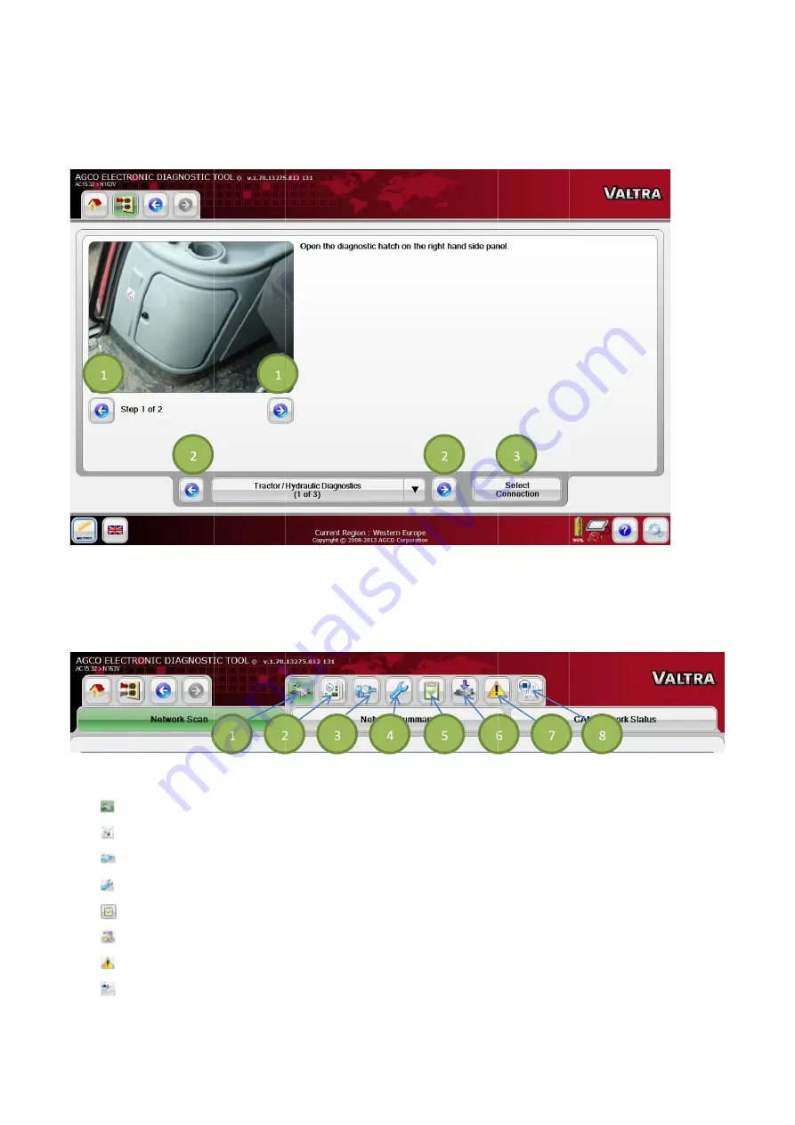
Scroll through the steps (1) for further instruction on the connection points. Navigate through the connections
using the left
NOTE: The EDT can be ON when connecting to a vehicle. The vehicle must be OFF during connection of the EDT to
the vehicle’s diagnostic port.
FIG.94
A group of navigation icons appears after the Diagnostics Connection page
until after a vehicle has been selected. The selected icon will be highlighted in green.
(1)
Network Scan (
(2)
Diagnostic by Function
(3)
Calibration
(4)
Configuration
(5)
Diagnostic Test
(6)
Software Flash
(7)
Diagnostic Trouble Co
(8)
CAN Trace
DIAGNOSTIC CONNECTIO
After the desired model is selected, the screen will display
Scroll through the steps (1) for further instruction on the connection points. Navigate through the connections
left
and right arrow icons (2). Select the desired connection by selecting the
The EDT can be ON when connecting to a vehicle. The vehicle must be OFF during connection of the EDT to
the vehicle’s diagnostic port.
A group of navigation icons appears after the Diagnostics Connection page
until after a vehicle has been selected. The selected icon will be highlighted in green.
Network Scan (Set by default after the vehicle connection point is selected)
Diagnostic by Function
Calibration
Configuration
Diagnostic Test
Software Flash
Diagnostic Trouble Co
CAN Trace
DIAGNOSTIC CONNECTION SELECTION
After the desired model is selected, the screen will display
Scroll through the steps (1) for further instruction on the connection points. Navigate through the connections
arrow icons (2). Select the desired connection by selecting the
The EDT can be ON when connecting to a vehicle. The vehicle must be OFF during connection of the EDT to
the vehicle’s diagnostic port.
A group of navigation icons appears after the Diagnostics Connection page
until after a vehicle has been selected. The selected icon will be highlighted in green.
Set by default after the vehicle connection point is selected)
Diagnostic by Function
Diagnostic Trouble Codes
N SELECTION
After the desired model is selected, the screen will display
Scroll through the steps (1) for further instruction on the connection points. Navigate through the connections
arrow icons (2). Select the desired connection by selecting the
The EDT can be ON when connecting to a vehicle. The vehicle must be OFF during connection of the EDT to
A group of navigation icons appears after the Diagnostics Connection page
until after a vehicle has been selected. The selected icon will be highlighted in green.
Set by default after the vehicle connection point is selected)
N SELECTION
After the desired model is selected, the screen will display the available connections.
Scroll through the steps (1) for further instruction on the connection points. Navigate through the connections
arrow icons (2). Select the desired connection by selecting the
The EDT can be ON when connecting to a vehicle. The vehicle must be OFF during connection of the EDT to
A group of navigation icons appears after the Diagnostics Connection page
until after a vehicle has been selected. The selected icon will be highlighted in green.
Set by default after the vehicle connection point is selected)
the available connections.
Scroll through the steps (1) for further instruction on the connection points. Navigate through the connections
arrow icons (2). Select the desired connection by selecting the Select Connect
The EDT can be ON when connecting to a vehicle. The vehicle must be OFF during connection of the EDT to
A group of navigation icons appears after the Diagnostics Connection page. These options are not available
until after a vehicle has been selected. The selected icon will be highlighted in green.
Set by default after the vehicle connection point is selected)
Scroll through the steps (1) for further instruction on the connection points. Navigate through the connections
Select Connect
The EDT can be ON when connecting to a vehicle. The vehicle must be OFF during connection of the EDT to
. These options are not available
49
Scroll through the steps (1) for further instruction on the connection points. Navigate through the connections
Select Connection icon (3).
The EDT can be ON when connecting to a vehicle. The vehicle must be OFF during connection of the EDT to
. These options are not available
49
Scroll through the steps (1) for further instruction on the connection points. Navigate through the connections
The EDT can be ON when connecting to a vehicle. The vehicle must be OFF during connection of the EDT to
. These options are not available
Содержание EDT
Страница 1: ...1 SERVICE TOOL OPERATOR MANUAL Electronic Diagnostic Tool EDT 22 01 2014...
Страница 2: ...2 2...


