background image

8

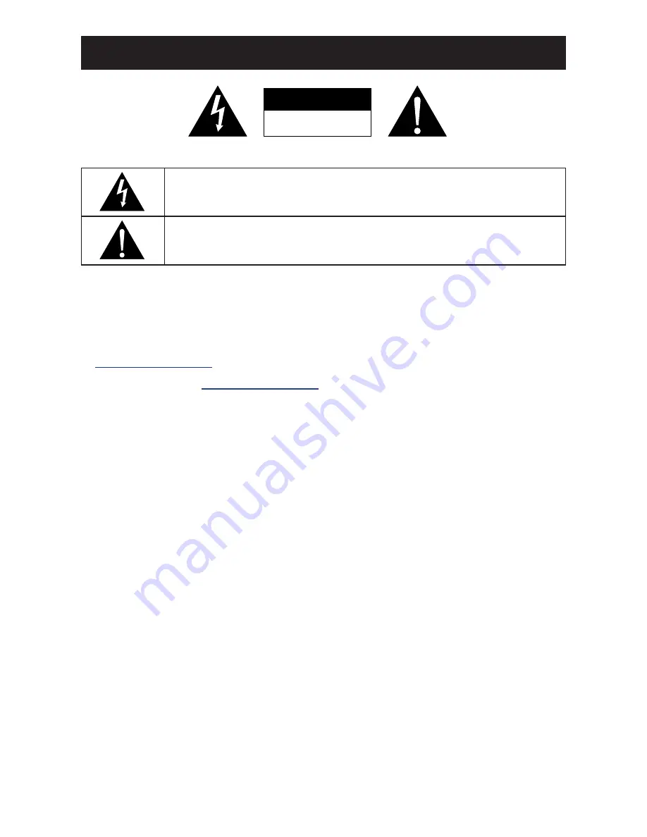
CAUTION

RISK OF ELECTRIC SHOCK

DO NOT OPEN

Symbols used in this manual

This icon indicates the existence of a potential hazard that could result in personal injury 
or damage to the product.

This icon indicates important operating and servicing information.

Notice

•  Read this User Manual carefully before using the LCD display and keep it for future reference.

• 

The product specifications and other information provided in this User Manual are for reference only. All 

information is subject to change without notice. Updated content can be downloaded from our web site at 

http://www.agneovo.com

.

•  To register online, go to 

http://www.agneovo.com

.

•  To protect your rights as a consumer, do not remove any stickers from the LCD display. Doing so may 

affect the determination of the warranty period.

Cautions When Setting Up

•  Do not place the LCD display near heat sources, such as a heater, exhaust vent, or in direct sunlight.

•  Do not cover or block the ventilation holes in the housing.

•  Place the LCD display on a stable area. Do not place the LCD display where it may subject to vibration or 

shock.

•  Place the LCD display in a well-ventilated area.

•  Do not place the LCD display outdoors.

•  To avoid the risk of shock or permanent damage to the set, do not expose the display to dust, rain, water or 

an excessively moist environment.

•  Do not spill liquid or insert sharp objects into the LCD display through the ventilation holes. Doing so may 

cause accidental fire, electric shock or damage the LCD display.

PRECAUTIONS

Содержание TX-32P

Страница 1: ...TX 32P TX 42P LED BacklitTouch Display User Manual ...

Страница 2: ...Preparing for the Installation 12 1 3 Moving the Display 12 1 3 1 Unpacking the Display 12 1 3 2 Carrying the Display 13 1 3 3 Setting Down the Display 13 1 3 4 Placing the Display 13 1 4 Installing and Removing Table Stands optional 14 1 5 Wall Mounting Installation 15 1 5 1 VESA Grid 15 1 5 2 Ventilation Requirements for Enclosure Locating 16 1 6 Mounting in Portrait Position 16 1 7 LCD Display ...

Страница 3: ...ting the Volume 29 3 4 Setting Up the IR Sensor For TX 42P only 30 CHAPTER 4 ON SCREEN DISPLAY MENU 31 4 1 Using the OSD Menu 31 4 2 OSD Menu Tree 33 CHAPTER 5 ADJUSTING THE LCD DISPLAY 34 5 1 Color 34 5 2 Image Setting 36 5 3 OSD Menu 37 5 4 Signal Source 38 5 5 Audio 38 5 6 Special 40 CHAPTER 6 APPENDIX 41 6 1 Warning Messages 41 6 2 Supported Resolution 41 6 3 Cleaning 43 6 4 Troubleshooting 44...

Страница 4: ... or relocate the receiving antenna Increase the separation between the equipment and receiver Connect the equipment into an outlet on a circuit different from that to which the receiver is connected Consult the dealer or an experienced radio TV technician for help Changes or modifications not expressly approved by the party responsible for compliance could void the user s authority to operate the ...

Страница 5: ...ctuation and Flicker EN 50581 2012 Technical documentation for the assessment of electrical and electronic products with respect to the restriction of hazardous substances EN 50564 2011 Electrical and electronic household and office equipment Measurement of low power consumption following provisions of directives applicable 2006 95 EC Low Voltage Directive 2004 108 EC EMC Directive 2009 125 EC ErP...

Страница 6: ...ments of standards PN 93 T 42107 and PN 89 E 06251 Electric Magnetic and Electromagnetic Fields EMF We manufacture and sell many products targeted at consumers which like any electronic apparatus in general have the ability to emit and receive electromagnetic signals One of our leading Business Principles is to take all necessary health and safety measures for our products to comply with all appli...

Страница 7: ... BS 1362 5A A S T A or BSI approved type 3 Refit the fuse cover If the fitted plug is not suitable for your socket outlets it should be cut off and an appropriate 3 pin plug fitted in its place If the mains plug contains a fuse this should have a value of 5A If a plug without a fuse is used the fuse at the distribution board should not be greater than 5A Note The severed plug must be destroyed to ...

Страница 8: ... with the letter L or coloured RED Before replacing the plug cover make certain that the cord grip is clamped over the sheath of the lead not simply over the three wires North Europe Nordic Countries Information Placering Ventilation VARNING FÖRSÄKRA DIG OM ATT HUVUDBRYTARE OCH UTTAG ÄR LÄTÅTKOMLIGA NÄR DU STÄLLER DIN UTRUSTNING PÅPLATS Placering Ventilation ADVARSEL SØRG VED PLACERINGEN FOR AT NE...

Страница 9: ...sal organization that serves your household or the store at which you purchased the product Attention users in United States Please dispose of according to all Local State and Federal Laws For the disposal or recycling information contact www mygreenelectronics com or www eiae org End of Life Directives Recycling Your new Public Information Display contains several materials that can be recycled f...

Страница 10: ...ery is to be returned to the selling point For other non EU countries Please contact your local authority for correct method of disposal of the used battery According to EU directive 2006 66 EC the battery can t be disposed improperly The battery shall be separated to collect by local service Turkey RoHS Türkiye Cumhuriyeti EEE Yönetmeliğine Uygundur Ukraine RoHS Обладнання відповідає вимогам Техн...

Страница 11: ...tect your rights as a consumer do not remove any stickers from the LCD display Doing so may affect the determination of the warranty period Cautions When Setting Up Do not place the LCD display near heat sources such as a heater exhaust vent or in direct sunlight Do not cover or block the ventilation holes in the housing Place the LCD display on a stable area Do not place the LCD display where it ...

Страница 12: ... wet hands When turning off the display by detaching the power cord wait 6 seconds before re attaching the power cord for normal operation Do not knock or drop the display during operation or transportation Cleaning and Maintenance To protect your display from possible damage do not put excessive pressure on the LCD panel When moving your display grasp the frame to lift do not lift the display by ...

Страница 13: ...y for extended periods of time It can be several hours or several days Use a screen saver and run it for extended periods of time Use a black and white image and run it for extended periods of time There are millions of micro transistors inside the LCD display It is normal for a few transistors to be damaged and to produce spots This is acceptable and is not considered a failure IMPORTANT Always a...

Страница 14: ...9 BACKMUSIC 0 VOL USB cable Remote control TX 32P TX 42P www agneovo com TX 32P TX 42P_Quick Guide_V010 Quick Start Guide TX 32P TX 42P LED Backlit Touch Display Quick Start Guide LCD Display Audio cable Note Remote control is shipped with the supplied AAA batteries For all other regions apply a power cord that conforms to the AC voltage of the power socket and has been approved by and complies wi...

Страница 15: ...er 5000m in altitude In installations at altitudes above 3000m some abnormalities may be experienced 1 3 Moving the Display 1 3 1 Unpacking the Display Before unpacking the display prepare a flat and stable surface near a wall outlet Set the product box in an upright position according to the arrow markings on the outside of the product box 1 Open the product box from the top of the box 2 Take the...

Страница 16: ...and stable surface covered by a protective sheet and a table cushion as shown in the illustration provided 1 3 4 Placing the Display When placing the display keep the display upright Never tilt the display towards the left right or balanced on a single corner of the frame Caution Avoid applying force or using sharp objects on the LCD panel at all times Caution Never press or place anything on the ...

Страница 17: ...n the stand by the screw holes and then tighten the supplied screws on both sides of the display Screws Table stand Longer portions face the front To remove table stands 1 Power off the display 2 Spread a protective sheet on a flat surface 3 Carefully place the display face down on the protective sheet 4 Remove screws using a screwdriver and place them in a safe place for reuse Note The longer sid...

Страница 18: ...mproper installation For the wall mounting kit use M6 mounting screws having a length 10 mm longer than the thickness of the mounting bracket and tighten them securely Unit weight 12 5 kg TX 32P or 24 5 kg TX 42P The equipment and its associated mounting means still remain secure during the test For use only with UL Listed Wall Mount Bracket with minimum weight load 12 5 kg TX 32P or 24 5 kg TX 42...

Страница 19: ...ure to consult the bracket manufacturer for installation location 1 5 2 Ventilation Requirements for Enclosure Locating To allow heat to disperse leave space between surrounding objects as shown in the diagram below 40 mm 40 mm 40 mm 40 mm 1 6 Mounting in Portrait Position This display can be installed in portrait position 1 Remove the table stand if attached 2 Rotate 90 degrees counter clockwise ...

Страница 20: ...17 PRODUCT DESCRIPTION 1 7 LCD Display Overview 1 7 1 Control Panel AUTO MINUS PLUS MENU POWER 1 5 7 6 4 3 2 TX 32P AUTO MINUS PLUS MENU POWER 1 5 7 6 4 3 2 TX 42P ...

Страница 21: ...level while OSD menu is off Navigates through the OSD menu items Increases the adjustment while OSD menu is on 4 MENU Displays the On Screen Display OSD menu Selects items or accepts the settings made in the OSD menu 5 POWER Turns the power on off Note POWER button does not function if the Main Power switch is off 6 IR sensor indicator Displays the status of the IR sensor Green The display s power...

Страница 22: ...19 PRODUCT DESCRIPTION 1 7 2 Input Output Terminals 4 5 6 7 8 9 2 1 3 TX 32P 1 4 5 6 7 8 9 2 3 TX 42P ...

Страница 23: ...udio devices Note Headphones and earphones are not supported 5 Audio in Connects with the audio out connector of a video source such as a computer VCR or DVD player when the display is connected to the source via the VGA or DVI connector 6 VGA Connects with the analog video output VGA of a computer 7 DVI Connects with the digital video output of a computer and other applicable devices 8 HDMI Conne...

Страница 24: ...icator is not lit then the controls will not function 2 MENU Displays the OSD menu Please refer to page 34 3 NAVIGATION buttons Navigates through menus selects items and adjusts values 4 EXIT Exits the current menu 5 ENTER Selects items or accepts the settings made in the OSD menu 6 SOURCE Switches the video input source Use the buttons to select HDMI DVI or VGA and press the ENTER button to confi...

Страница 25: ...the remote control within the range which is shown in the following table Model Operation Angle RC operational distance TX 32P θ 30º for H V 3m TX 42P θ 30º for H V 1m 30 30 Caution The incorrect use of batteries can result in leaks or bursting Be sure to follow these instructions Place AAA batteries matching the and signs on each battery to the and signs of the battery compartment Do not mix batt...

Страница 26: ... or personal injury When unplugging the power cord hold the power cord by the plug head Never pull by the cord Loose connections may cause noise Do not plug and unplug the power cord repeatedly in a short period of time When disconnecting the AC power cord be sure to first disconnect the plug from the outlet socket CHAPTER 2 MAKING CONNECTIONS Note The supplied power cord varies depending on the c...

Страница 27: ...d the other end of an audio cable to the AUDIO OUT connector of the computer 3 Press the SOURCE button on the remote control to select the video input source D SUB 4 Press the MENU button to display the OSD menu and select Audio Audio Select to set the audio input source as PC Computer VGA OUT D Sub 15 pin VGA AUDIO OUT AUDIO IN 2 2 2 Using HDMI Input Connect one end of an HDMI cable to the HDMI c...

Страница 28: ...f the LCD display and the other end of a DVI cable to the DVI OUT connector of the computer 2 For audio input connect one end of an audio cable to the AUDIO IN connector of the LCD display and the other end of an audio cable to the AUDIO OUT connector of the computer 3 Press the SOURCE button on the remote control to select the video input source DVI Once selected the audio input setting will auto...

Страница 29: ...erate the computer by tapping swiping or scrolling the display USB USB Computer TX 32P USB USB Computer TX 42P Note The touch driver will be installed automatically for the systems running Microsoft Windows 7 Windows 8 Windows 10 Linux 2 6 3 6 Mac OS OSX and Android 2 3 or above Certain touch gestures such as zoom in zoom out and rotate may not work depending on the application or software your co...

Страница 30: ... and the other end of an audio cable to the AUDIO IN connector of the audio device 2 3 Connecting External Equipment DVD DVD B 2 3 1 Using HDMI Video Input Connect one end of an HDMI cable to the HDMI connector of the LCD display and the other end of an HDMI cable to the HDMI OUT connector of the video player DVD DVD B HDMI HDMI OUT DVD DVD B AUDIO OUT Audio Device AUDIO IN ...

Страница 31: ...on a menu with available input sources will be displayed on the screen D SUB DVI HDMI Auto Search 640 X480 60Hz If the selected input source signal is not connected to the LCD display or is turned off the no signal message is displayed on the screen No Signal Input D SUB 1 Press the SOURCE button 2 Press the or button to choose the input source then press the ENTER button CHAPTER 3 USING THE LCD D...

Страница 32: ...e After pressing the or button the volume adjustment bar is displayed on the screen automatically 2 Volume Press the MUTE button to mute the audio POWER F1 F2 F3 F4 MUSIC 2 MOVIE 3 PHOTO 1 ROTATE 5 16 9 4 3 4 ENTER MENU MUTE SLIDE SHOW SOURCE EXIT 6 OSD 8 ZOOM 7 9 BACKMUSIC 0 VOL VOLUME buttons ...

Страница 33: ... rear of the display as illustrated below To set up the IR sensor do the following 1 Remove the two screws securing the IR sensor to the LCD display and loosen the IR sensor 2 Unthread the cables from the cable clip 3 Attach the IR sensor to the desired position on display using the magnets located on the sensor Reverse the steps to return the sensor to its original position IR sensor Magnets ...

Страница 34: ...menu 1 Press the or button to select the main menu item 2 Press the ENTER button to enter the submenu 3 Adjust the settings The highlighted item indicates the active submenu For example 8 Clock Phase H Position V Position 640 X480 60Hz 640 X480 60Hz Clock Phase H Position V Position 1 Press the PLUS or MINUS button to select the submenu item 2 Press the MENU button to enter the adjustment mode 3 P...

Страница 35: ... button repeatedly if necessary Press the EXIT button repeatedly if necessary When settings are modified all changes are saved when the user does the following Proceeds to another menu Exits the OSD menu Waits for the OSD menu to disappear Note Availability of some menu items depend on the input source signal ...

Страница 36: ...p See page 34 2 Image Setting Clock Phase Sharpness For TX 32P only H Position V Position See page 34 3 OSD Menu OSD H Pos OSD V Pos OSD Timer Language ANTI Burn in See page 37 4 Signal Source D SUB DVI HDMI Auto Search See page 38 5 Audio Volume Mute Audio Select See page 38 6 Special Aspect Ratio Reset Auto Monitor Id See page 40 Note Availability of some menu items depend on the input source si...

Страница 37: ...the button on the remote control to select an option 4 Press the MENU button on the control panel or the ENTER button on the remote control to enter the adjustment mode Item Function Operation Range Contrast Adjusts the contrast of the display Press the PLUS MINUS button on the control panel or the button on the remote control to adjust the value 0 to 100 Original Setting High Setting Low Setting ...

Страница 38: ...select Red Green or Blue b Press the MENU button on the control panel or the ENTER button on the remote control c Press the PLUS MINUS button on the control panel or the button on the remote control to adjust the value 0 to 100 Color Temp Adjusts the color temperature of the display Press the PLUS MINUS button on the control panel or the button on the remote control to select the setting For TX 32...

Страница 39: ...lock Adjusts the time of the internal clock Press the PLUS MINUS button on the control panel or the button on the remote control to adjust the value 0 to 100 Phase Adjusts the frequency phase of the display Press the PLUS MINUS button on the control panel or the button on the remote control to adjust the value 0 to 100 Sharpness Adjusts the picture sharpness of the display Note This item is availa...

Страница 40: ...he PLUS MINUS button on the control panel or the button on the remote control to adjust the value 0 to 100 OSD Timer Changes the OSD menu timer settings where the number selected for this setting equals the number of seconds the OSD menu is displayed before it automatically closes if 0 is selected the OSD menu will not close automatically Press the PLUS MINUS button on the control panel or the but...

Страница 41: ...mage Setting OSD Menu Signal Source Audio Special 640 X480 60Hz 2 Volume Mute Audio Select 640 X480 60Hz 1 Press the MENU button on the control panel or the remote control to call out the OSD window 2 Select Audio then press the MENU button on the control panel or the ENTER button on the remote control 3 Press the PLUS MINUS button on the control panel or the button on the remote control to select...

Страница 42: ...DJUSTING THE LCD DISPLAY Item Function Operation Range Audio Select Chooses an audio source Press the MENU button on the control panel or the ENTER button on the remote control to select the setting HDMI PC ...

Страница 43: ... the adjustment mode Item Function Operation Range Aspect Ratio Adjusts the aspect ratio of the display as follows OFF Original size ON Full screen Press the MENU button on the control panel or the ENTER button on the remote control to select the setting ON OFF Reset Resets the display to its factory default settings Press the MENU button on the control panel or the ENTER button on the remote cont...

Страница 44: ...onnected Check if any pin inside the cable connector is twisted or broken 6 2 Supported Resolution VGA Resolution Resolution Refresh Rate Hz Horizontal Frequency KHz Pixel Frequency MHz Standard Type 640x480 60 31 5 25 175 Industrial Standard 75 37 5 31 5 VESA Standard 800x600 60 37 9 40 VESA Guideline 72 48 1 50 VESA Standard 75 46 9 49 5 VESA Standard 1024x768 60 48 4 65 VESA Guideline 70 56 5 7...

Страница 45: ...ity is optimum in HD 1080 mode 1920x1080 60Hz Your PC display screen might appear different depending on the manufacturer and your particular version of Windows Check your PC instruction book for information about connecting your PC to a display When horizontal synchronous signals seem irregular in RGB mode check PC power saving mode or cable connections The display settings table complies to the ...

Страница 46: ...If the surface becomes dirty soak a soft lint free cloth in a mild detergent solution Wring the cloth to remove excess liquid Wipe the surface of the display to remove dirt Then use a dry cloth of the same type to dry Do not scratch or hit the surface of the panel with fingers or hard objects of any kind Do not use volatile substances such as insert sprays solvents and thinners Cabinet Cleaning In...

Страница 47: ...n Can hear sound but no picture Improperly connected source signal cable Make sure that both video inputs and sound inputs are correctly connected Can see picture but no sound is heard Improperly connected source signal cable Volume is turned all the way down MUTE function is turned on No external speaker connected Make sure that both video and sound inputs are correctly connected Press the or but...

Страница 48: ...arton 1 Put all the accessories in the box if necessary 2 Place the lower foam cushion a inside the box 3 Place the monitor inside the supplied protective bag c 4 Place the LCD display down in the box 5 Place the upper foam cushion b on top of the LCD display 6 Place the accessories box on the designated area if necessary a TX 32P TX 42P b c ...

Страница 49: ...978 5 L x 578 2 W x 82 1 D Border Width U D R L mm 34 9 34 9 23 8 23 8 24 92 24 92 24 13 24 13 Weight kg 12 5 24 5 I O TX 32P TX 42P Basic I O VGA x 1 DVI x 1 HDMI x 1 RS232 x 1 Audio Audio In x 1 Audio Out x 1 Speaker x 2 10W Output USB 1 1 x 1 Touch TX 32P TX 42P Touch Sensor PCAP 10 points Smallest Distance between 2 Points Converging zoom 9mm Vertical and Horizontal 12mm Diagonal 15mm φ9 coppe...

Страница 50: ...42P Operation Temp C 0 C 40 C Power consumption Watt 20 C 60 C Storage Humidity 20 80 RH Operating Humidity 20 80 RH Display Orientation Landscape Portrait Usage hrs days 24 7 Note All specifications are subject to change without prior notice ...

Страница 51: ...2 3 174 174 M6xL10 x4 37 STD 03 x2 Option 7 2 2 TX 42P Dimensions 400 289 7 289 7 124 3 330 124 8 200 258 7 462 258 7 982 3 outline dimension 932 2 opening dimension 23 6 26 9 582 outline dimension 525 3 opening dimension 26 9 26 9 23 6 34 7 71 7 258 7 462 258 7 M6XL10 x4 AG Neovo Company Address 5F 1 No 3 1 Park Street Nangang District Taipei 11503 Taiwan Copyright 2017 AG Neovo All rights reserv...

Отзывы: