Installation, assembly & setting
Assembly instructions
EN
CS 16 - CS 20
Date 01.06.2021
Version 6.0
43–64
End position control for entire stroke range
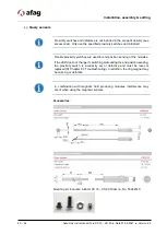
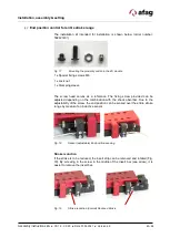
The installation kit intended for installation is shown below (order number:
50242140!).
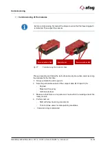
Fig. 17
Mounting the proximity switch in the ZA module
1 x Special fixing screws M6
1 x Lock nut
1 x Clamping sleeve
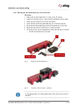
The screw head serves as a reference. The fixing screw provided can be
adjusted depending on the combination with the shock absorber. Due to the
adjustability of the screw, the end position can be sensed over the entire stroke
range by means of an inductive sensor.
Fig. 18
Sensor (adjustable) End position sensing
Stroke reduction
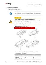
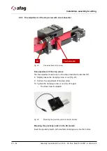
If the stroke is to be reduced, the insert strip can be removed and rotated (Fig.
19). By screwing in the screw in the middle of the insert bar (see arrow), it is
easier to remove the insert bar.
Fig. 19
Stroke reduction (normal) Reduced stroke

