background image


Index


62 – 64 

Assembly instructions EN  


CS 16 - CS 20  


Date 01.06.2021  

  Version 6.0


Index 

A


Assembly ........................................................... 33 

C


Changes & Modifications ................................... 12 
Commissioning of the rotary modules ............... 51 
Compressed air specification ............................ 57 

D


Decommissioning .............................................. 59 
Disposal ....................................................... 59, 60 

E


Explanation of symbols ........................................ 6 

F


Fault causes and remedy .................................. 54 
Foreseeable misuse ............................................ 9 

H


Hearing protection ............................................. 12 

I


Installation .......................................................... 33 
Instructions .......................................................... 7 

M


Maintenance intervals ........................................ 56 

O


Obligations and liability ..................................... 10 
Obligations of the operating company .............. 10 
Obligations of the personnel ............................. 11 
Operator ............................................................ 11 

P


Packaging ......................................................... 28 
Personal protective equipment (PPE)............... 12 
Personnel qualifications .................................... 11 
Personnel requirements .................................... 11 
Protective clothing............................................. 12 
Protective gloves............................................... 12 

Q


Qualified personnel ........................................... 11 

R


Reports, certificates, plans ................................. 8 
Residual risks .................................................... 13 

S


Safety instructions......................................... 9, 55 
Safety shoes ..................................................... 12 
Setting ............................................................... 33 
Storage ............................................................. 28 

W


Warranty ............................................................. 8 


Содержание 50100711

Страница 1: ...ating instructions Compact Slide CS 16 CS 20 Translation of the Original Assembly Instructions EN CS 16 30 Order no 50167742 CS 16 60 Order no 50154069 CS 16 90 Order no 50154070 CS 16 120 Order no 50154071 CS 20 50 Order no 50100711 CS 20 100 Order no 50100712 CS 20 150 Order no 50100713 ...

Страница 2: ...e of the art Due to the constant technical development and improvement of our products we reserve the right to make technical changes at any time Updates of our documentations Unlike the printed documents our digital instructions manuals product data sheets and catalogues are being continuously updated on our website Please keep in mind that the digital documents on our website are always the late...

Страница 3: ...nts 11 2 5 1 Personnel qualification 11 Personal protective equipment PPE 12 Changes and modifications 12 General hazards residual risks 13 2 8 1 General hazards at the workplace 13 2 8 2 Danger due to electricity 14 2 8 3 Mechanical hazards 14 2 8 4 Danger due to pneumatics 15 2 8 5 Danger caused by omitting maintenance work 15 3 Technical data 16 Compact Slide CS 16 16 3 1 1 Dimensional drawing ...

Страница 4: ... 41 6 6 1 Safety notes for settings 41 6 6 2 Adjusting the shock absorbers and stop screws 42 End position control for entire stroke range 43 Sequence of the intermediate position 44 6 8 1 Sequence of intermediate positions during extension 44 6 8 2 Sequence of intermediate positions during retraction 45 ZA intermediate stop option 46 6 9 1 ZA intermediate stop overview CS 16 and CS 20 46 6 9 2 Mo...

Страница 5: ...air 55 Maintenance activities and maintenance intervals 56 9 3 1 Overview of the maintenance points 56 9 3 2 Compressed air specifications 57 9 3 3 Further maintenance 58 Spare and wear parts lists repairs 58 9 4 1 General notes 58 9 4 2 Safety instructions 58 10 Decommissioning disassembly disposal 59 Safety instructions for decommissioning disassembling and disposal 59 Decommissioning 59 Disasse...

Страница 6: ...lide The illustrations in this manual shall provide you with a basic understanding of the module and may vary from the actual design of your module Explanation of symbols The safety notes are marked by a pictogram and a signal word The safety notes describe the extent of the hazard DANGER Danger This safety note indicates an imminently hazardous situation which if not avoided will result in death ...

Страница 7: ... the various potential health risks Warning Dangerous electrical voltage Warning Risk of injury from contact with hot surfaces Warning Risk of hand and finger injury due to uncontrolled movements of components Warning Risk of injury as a result of parts being flung out Warning high noise levels Additional symbols In these assembly instructions the following symbols are used to highlight instructio...

Страница 8: ...tive accessories and wear parts Normal wear and tear are excluded from the warranty The warranty shall expire in the following cases Improper use of the module Non observance of the instructions regarding assembly commissioning operation and maintenance of the module Improper assembly commissioning operation and maintenance Repairs and design changes carried out without prior technical instruction...

Страница 9: ... up to a maximum of CS 16 2 0 3 0 kg CS 20 up to 5 0 kg Load capacities at the front of the modules CS 16 1 5 2 0 kg CS 20 up to 4 0 kg The CS compact slides can be used in combination with other modules as a pick and place station whereby the permissible load capacity must not be exceeded Any use of the compact slide beyond the described purpose is considered to be not in accordance with the inte...

Страница 10: ...ary professional qualifications and experience are familiar with the basic rules regarding occupational safety and accident prevention have been instructed in the correct handling of the compact slide have read and understood these assembly instructions The operating company is also required to monitor on an ongoing basis that the personnel work safely considering any potential hazard involved and...

Страница 11: ...se of the compact slide thus exposing himself and others to the risk of serious injury Therefore only qualified personnel may be permitted to carry out the described activities on the compact slide Persons whose ability to react is restricted due to the intake of medication or the like must not interact with the compact slide These installation instructions are intended for skilled personnel insta...

Страница 12: ...spective mandatory signs Protective clothing is a close fitting clothing specifically designed to protect personnel from hazards during work Protective gloves are specifically designed to protect the personnel against hand injuries such as cuts abrasion burns Safety shoes are specifically designed to protect the personnel against foot injuries from crushing falling objects or slipping on slippery ...

Страница 13: ...e may cause the following hazards to the personnel danger to life and limb of the operator or third parties to the compact slide itself property damage Always keep the assembly instructions ready at hand at the workplace Please also observe the general and local regulations on accident prevention and environmental protection the safety information sheet for the CS module WARNING Danger Do not use ...

Страница 14: ...ce WARNING Danger Risk of electric shock If work on electrical components is required ensure that the work is carried out properly failure to do so will cause serious or fatal injuries Work on the machine s electrical equipment may only be performed by skilled electrician or trained personnel under the supervision of a skilled electrician in accordance with all relevant electrical regulations WARN...

Страница 15: ...l injuries if the work is carried out improperly Only qualified personnel may work with or on the pneumatic system The necessary personal protective equipment must be provided and used CAUTION Danger of injury Poor or not regularly performed maintenance work may cause malfunction of the components which may result in injuries The due diligence obligations of the operating company include ensuring ...

Страница 16: ...Technical data 16 64 Assembly instructions EN CS 16 CS 20 Date 01 06 2021 Version 6 0 3 Technical data Compact Slide CS 16 3 1 1 Dimensional drawing CS 16 Fig 1 Dimensional drawing Compact Slide CS 16 ...

Страница 17: ...bly instructions EN CS 16 CS 20 Date 01 06 2021 Version 6 0 17 64 3 1 2 Technical data CS 16 Fig 2 Table technical data CS 16 The maximum load capacities are listed in the table in the section Slide loads Slide loads 3 1 4 ...

Страница 18: ...Technical data 18 64 Assembly instructions EN CS 16 CS 20 Date 01 06 2021 Version 6 0 3 1 3 Preferred combinations CS 16 ...

Страница 19: ...Technical data Assembly instructions EN CS 16 CS 20 Date 01 06 2021 Version 6 0 19 64 3 1 4 Slide loads CS 16 Fig 3 Table of slide loads CS 16 ...

Страница 20: ...Technical data 20 64 Assembly instructions EN CS 16 CS 20 Date 01 06 2021 Version 6 0 3 1 5 Operation time diagram CS 16 ...

Страница 21: ...Technical data Assembly instructions EN CS 16 CS 20 Date 01 06 2021 Version 6 0 21 64 Compact Slide CS 20 3 2 1 Dimensional drawing CS 20 Fig 4 Dimensional drawing Compact Slide CS 20 ...

Страница 22: ... Assembly instructions EN CS 16 CS 20 Date 01 06 2021 Version 6 0 3 2 2 Technical data CS 20 Fig 5 Table technical data CS 20 The maximum load capacities are listed in the table in the section Slide loads slide loads 3 2 4 ...

Страница 23: ...Technical data Assembly instructions EN CS 16 CS 20 Date 01 06 2021 Version 6 0 23 64 3 2 3 Preferred combinations CS20 ...

Страница 24: ...Technical data 24 64 Assembly instructions EN CS 16 CS 20 Date 01 06 2021 Version 6 0 3 2 4 Slide loads CS 20 Fig 6 Table of slide loads CS 20 ...

Страница 25: ...Technical data Assembly instructions EN CS 16 CS 20 Date 01 06 2021 Version 6 0 25 64 3 2 5 Operation time diagram CS 20 ...

Страница 26: ... safety instructions in Chapter 2 Safety instructions in this manual CAUTION Danger of injury when unpacking the rotary modules The compact slides are packed in the original packaging cardboard box If handled incorrectly the module may fall out of the box when unpacked and cause limb injuries Carefully unpack the compact slides NOTICE Risk of material damage to shock absorbers The shock absorbers ...

Страница 27: ...2 x Shock absorber SD M8x1 4 2 x Shock absorber SD M10x1 5 2 x Centering bushing Ø 7x3 mm 2 x Centering bushing Ø 9x4 mm 4 x Special screw M4x20 8 mm 4 x Special screw M6x25 9 mm 2 x Stop sleeve ASH M10x1 1 2 x Stop sleeve ASH M12x1 1 Transport No liability can be assumed for damages caused by improper installation on the part of the operating company The following conditions must be complied with...

Страница 28: ...this symbol Centre of gravity This symbol marks the centre of gravity of the packages pay attention to the position of the centre of gravity Storage If the compact slide is stored for an extended period of time observe the following Do not store the compact slides outdoors or expose them to weather conditions The storage space must be dry and dust free Room temperature of the storage space 0 50 C ...

Страница 29: ...ion devices In order ensure safe and reliable operation it is important that the modules are handled with care The compact slides are highly compact pneumatic modules and are used for the shock free rotation of permanently mounted loads in the defined ambient and operating conditions The assembly position of the compact slide can be vertical or horizontal The CS 16 CS 20 modules consists of the ba...

Страница 30: ...or INI c10x28 5 Em PNP NO M8x1 50033432 Initiator INI d4x25 Sn1 0 PNP NO M8x1 11016714 Initiator INI c10x19 5 Em PNP NO M8x1 50313987 Initiator INI c10x9 Em PNP NO M8x1 50313986 Clamping nut M6x1 50042748 Shock absorber SD M8x1 4 50177008 Shock absorber SD M10x1 5 50337721 ZA intermediate stop ZA CA 16 50205052 ZA intermediate stop ZA CS 20 50205054 ...

Страница 31: ...Design and description Assembly instructions EN CS 16 CS 20 Date 01 06 2021 Version 6 0 31 64 ...

Страница 32: ...Design and description 32 64 Assembly instructions EN CS 16 CS 20 Date 01 06 2021 Version 6 0 You will find more information on the accessories for the compact slides on our website www afag com ...

Страница 33: ... unit and the compressed air system When connecting the compact slides to the control unit or the compressed air system sudden unpredictable movements may occur which can cause personal injury or property damage Installation may only be carried out by a qualified specialist Read carefully the assembly and safety instructions before working with or on the compact slides CAUTION Danger of injury whe...

Страница 34: ...body from below Mounting base body from top Centering bushing and hole grid CS 16 CS 20 Hole grid 15 x 30 mm 24 x 48 mm Thread Bore M4 M6 Centering bushing H7 7mm 9mm CAUTION Risk of injuries due to uncontrolled parts movements When installed in a vertical position unexpected movements may occur if the compact slide is not in its lowest position When installing in a vertical position always move t...

Страница 35: ... 3 Accessories Insert the centering bushings in two diagonally opposite holes of the attachment grid 6 2 2 Tightening torques for screws Use screws with the following minimum specifications for mounting Standard VDI 2230 Screw strength Category 8 8 Surface Galvanized blue oiled or greased Thread Tightening torque M3 1 1 1 4 Nm M4 2 6 3 3 Nm M5 5 2 6 5 Nm M6 9 0 11 3 Nm M8 21 6 27 3 Nm ...

Страница 36: ...with the supplied screw plugs WARNING Danger when connecting to pneumatics The pneumatic system can pose various hazards that can cause serious or fatal injuries if the work is carried out improperly Only qualified personnel may work with or on the pneumatic system The required protective equipment shall be provided and used NOTICE Functional impairment to leaking compressed air connections Unused...

Страница 37: ...021 Version 6 0 37 64 Fig 10 Pneumatic circuit diagram compact slide Fig 11 Pneumatic circuit diagram compact slide with ZA 1 Compressed air connection 4 Throttle valve 2 Maintenance unit 5 Compact Slide CS 16 CS 20 3 5 3 5 2 Way valve 6 ZA intermediate stop 1 2 3 4 5 5 4 3 1 2 6 ...

Страница 38: ...cessories Fig 12 A B Holder of inductive initiators Fig 13 Mounting the inductive initiator How to mount the inductive initiator 1 Screw the initiator Fig 13 1 with the clamping sleeve Fig 13 2 into the holder A and B Fig 12 2 Adjust and tighten initiator Fig 13 1 together with shock absorber Fig 13 3 3 Connect the initiator to the control unit 4 Check initiator for correct function via initiator ...

Страница 39: ...ossible however interference with position sensing may result Fig 14 Installation and adjustment of the compact slide 1 Proximity switch 2 Screw fastening of proximity switch 3 Screw fastening in slot 4 Clamping piece Mounting the proximity switch Proceed as follows to install the sensors 1 Insert the proximity switch Fig 14 1 with the mounted clamping piece into the C slot 2 Fasten the proximity ...

Страница 40: ...tches are used for end position sensing of the modules If the LED does not change its switching state during the end position sensing the proximity switch is incorrectly set or defective and must be reset or replaced Chapter 8 3 Troubleshooting In addition the ring magnet may be missing or defective In combination with magnetic field producing modules interference may occur when using the magnetic...

Страница 41: ... compact slides on the part of the operator WARNING Danger of injury due to uncontrolled movement of the equipment Uncontrolled movements of parts can cause injury to third parties and damage to property Ensure that there are no persons in the working area of the compact slides CAUTION Danger arising from work carried out improperly Improper adjustment work can cause injuries and damage to propert...

Страница 42: ...low loads or slow rotation speeds Fig 16 Reduced damper effect Replacing the shock absorbers To replace the shock absorbers switch off the compressed air supply so that the module does not make any uncontrolled movements NOTICE Exceeding the specified load capacities will destroy the compact slide module For a clean approach to the end positions an exhaust air throttle is required to adjust the st...

Страница 43: ...crew head serves as a reference The fixing screw provided can be adjusted depending on the combination with the shock absorber Due to the adjustability of the screw the end position can be sensed over the entire stroke range by means of an inductive sensor Fig 18 Sensor adjustable End position sensing Stroke reduction If the stroke is to be reduced the insert strip can be removed and rotated Fig 1...

Страница 44: ...switched off 2 P2 P4 Slide moves forward Catch switched off 3 P2 P3 Slide front Catch switched on 4 P1 P3 Slide moves to intermediate position Catch switched on 5 P1 Pulse on P2 venting for approx 0 2 sec Before displacing from the intermediate position both air chambers must be ventilated so that the empty air chamber is not pointed Otherwise the CS may be damaged 6 P4 Catch switched off 7 P1 P4 ...

Страница 45: ... Slide moves forward Catch switched off 3 P2 P3 Slide at front Catch switched on 4 P1 P3 Slide moves to intermediate position Catch switched on 5 P1 Pulse on P2 venting for approx 0 2 sec Before displacing from the intermediate position both air chambers must be ventilated so that the empty air chamber is not pointed Otherwise the CS may be damaged 6 P4 Catch switched off 7 P1 P4 Slide returns to ...

Страница 46: ...9 1 ZA intermediate stop overview CS 16 and CS 20 The installation set of the ZA intermediate stop consists of the following parts 1 x ZA intermediate stop 3 x Fastening screws 3 x Centering sleeves 1 x SD holder long version for ZA module Fig 20 Overview of the ZA intermediate stop C slots for sensors Latch ZA Screws Cent bushing ...

Страница 47: ...the short holder 4 Screw the SD onto the long SD holder Fig 21 in the same direction 5 Mount the ZA intermediate stop with the centering sleeves on the slide 6 Move the slide and check that the ZA is correctly mounted 7 If necessary Carry out a fine adjustment of the shock absorbers on the SD The ZA intermediate stop is mounted Fig 21 Mount the ZA intermediate stop Fig 22 Illustration of the ZA mo...

Страница 48: ...The fine adjustment can be set on the stop screw shock absorber SD 8 Slightly loosen the clamping screw or nut Fig 23 9 Perform fine adjustment of the stop screw 10 Tighten the clamping screw or nut Fig 23 again The stop screw is adjusted Fig 24 Mounting the proximity switch in the ZA module Mounting the proximity switch in the ZA module Insert the proximity switch with mounted clamping piece into...

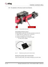
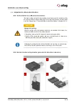
Страница 49: ...ties are described below in chapter 6 10 2 Changing the acting direction of the ZA Catch can be done in a simple way This activity must be performed before mounting on the CS module 6 10 2 ZA Catch to other acting direction procedure for retraction or extension CAUTION Danger of crushing When mounting a ZA intermediate position to an installed CS module the module or station must not be under pres...

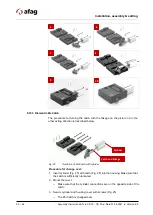
Страница 50: ...ion is described below Fig 25 Illustration of ZA Catch with cylinder Procedure for change over 1 Insert cylinder Fig 25 with catch Fig 25 into the housing Make sure that the catch is sufficiently lubricated 2 Mount the cover Make sure that the cylinder connections are on the opposite side of the catch 3 Secure cylinder and housing cover with screws Fig 25 The ZA Catch is changed over 5 6 7 8 9 10 ...

Страница 51: ...ponents Work on and with the compact slides may only be carried out by qualified personnel Make sure that there are no persons or tools in the working area of the rotary modules CAUTION Danger of injury in the working area of the compact slides During operation of the compact slides persons within the working area of the modules may be injured When operating the compact slides ensure a good overvi...

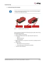
Страница 52: ...o P1 Fig 26 P1 slide extend 2 Loosen screw Fig 26 1 3 Adjust the position by turning the stop sleeve Fig 26 3 4 Adjust shock absorber by turning Fig 26 2 5 Loosen screw Fig 26 1a 6 Connect compressed air to P2 Fig 26 P2 slide retraction 7 Loosen screw Fig 26 1b 8 Adjust the position by turning the stop screw Fig 26 3 9 Adjust shock absorber by turning Fig 26 2 10 Fasten screw Fig 26 1b The prepara...

Страница 53: ...the instructions step by step when commissioning the modules for the first time 1 Slowly ventilate the entire system 2 Note the permissible values of the compact slide Chapter 3 for Payload Movement frequency mechanical stress 3 Make sure that there are no persons or tools within the working area of the rotary module 4 Perform test run Start with slow traversing movements Then continue under norma...

Страница 54: ...rts Fault Possible cause Remedy The compact slide strikes firmly in the end positions Stop shock absorber not set correctly Readjust stop shock absorber Firmly strike again in the end positions Damping elements defective Replace damping elements Chapter 5 3 Accessories The compact slide stops in an end position No signal on the proximity switch sensor Readjust proximity switch sensor The CS module...

Страница 55: ... in this manual WARNING Danger of injury due to improper maintenance Improperly carried out maintenance activities can cause considerable damage to property and serious injury The operator must exercise due care and only use trained maintenance personnel to carry out the activities Always wear personal protective equipment when carrying out maintenance and repair work WARNING Risk of injury due to...

Страница 56: ...e cloth do not spray with water Do not use aggressive cleaning agents 2 Shock absorber Check functioning Monthly On Check function of shock absorbers replace if necessary replacing after max 5 million load cycles 3 Compact Slide Check Monthly On Acoustic control for unusual noise generation Incorrectly adjusted missing or defective shock absorbers impair the function of the module and can lead to ...

Страница 57: ...ir we recommend that you use the following types of oil oil type Festo Special Oil Avia Avilub RSL 10 BP Energol HPL 10 Esso Spinesso 10 Shell Tellus Oel C 10 Mobil DTE 21 Blaser Blasol 154 Oil quantity 5 10 drops of oil per 1000 ltr Compressed air Viscosity range 9 to 11 mm2 s cST at 40 C ISO class VG 10 according to ISO 3448 NOTICE Risk of damage to property The operation of the compact slides w...

Страница 58: ...s a reliable repair service Defective modules can be sent to Afag for warranty repair within the warranty period After the warranty period has expired the customer can replace or repair defective modules or wear parts himself or send them to the Afag repair service Please note that Afag does not assume any warranty for modules that have not been replaced or repaired by Afag 9 4 2 Safety instructio...

Страница 59: ...nly be dismounted by qualified personnel WARNING Risk of injury due to improper decommissioning disassembly and disposal Improperly carried out activities can result in considerable material damage and serious injury The operator must exercise due care and only use specially trained and qualified personnel for this work CAUTION Risk of injury due to uncontrolled movements of the compact slides Whe...

Страница 60: ...e various components according to type of material and dispose of them properly Scrap the metallic materials Hand over plastic parts for recycling Sort the rest of the components by their material properties and dispose of them accordingly NOTICE Risk to the environment due to incorrect disposal of the compact slides Environmental damage can be caused by improper disposal of the compact slide Elec...

Страница 61: ... 1 6 4 1 7 1 7 4 1 7 4 2 Harmonised standards applied in particular EN ISO 12100 2010 Safety of machinery General principles for design Risk assessment and risk reduction Note The partly completed machinery must not be put into service until the machinery into which it is to be incorporated has been declared in conformity with the provisions of Machinery Directive 2006 42 EC The manufacturer under...

Страница 62: ...se 9 H Hearing protection 12 I Installation 33 Instructions 7 M Maintenance intervals 56 O Obligations and liability 10 Obligations of the operating company 10 Obligations of the personnel 11 Operator 11 P Packaging 28 Personal protective equipment PPE 12 Personnel qualifications 11 Personnel requirements 11 Protective clothing 12 Protective gloves 12 Q Qualified personnel 11 R Reports certificate...

Страница 63: ...g 12 A B Holder of inductive initiators 38 Fig 13 Mounting the inductive initiator 38 Fig 14 Installation and adjustment of the compact slide 39 Fig 15 Maximum damper effect 42 Fig 16 Reduced damper effect 42 Fig 17 Mounting the proximity switch in the ZA module 43 Fig 18 Sensor adjustable End position sensing 43 Fig 19 Stroke reduction normal Reduced stroke 43 Fig 20 Overview of the ZA intermedia...

Страница 64: ...64 64 Assembly instructions EN CS 16 CS 20 Date 01 06 2021 Version 6 0 ...

Отзывы: