


Installation, Operation & Maintenance Manual
IM-895
16
Troubleshooting Guidelines
(cont.)
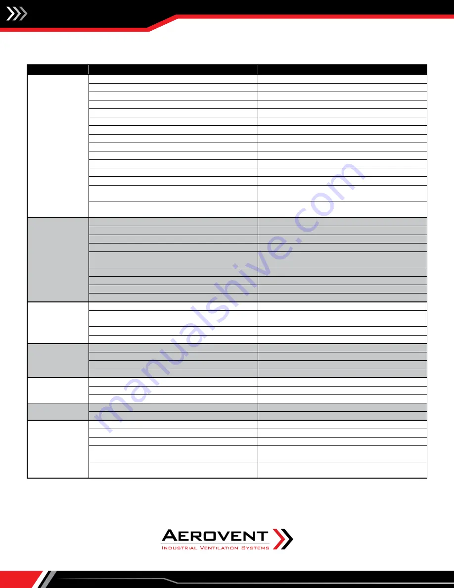
PROBLEM
POSSIBLE CAUSE
POSSIBLE REMEDY
D. Burner Not
Operating
1. See Problems "A" thru "C".
1. See Problems "A" and "C"
2. Damper end switch not functioning
2. Check and/or replace
3. Failed air flow switch
3. Check and/or replace
4. Loose wiring connection at air proving
4. Check and tighten
5. No pilot
5. See Problem "F"
6. Flame safeguard in lockout mode
6. Check and reset
7. High limit tripped
7. Check and/or replace
8. Too high or low gas pressure
8. Check pressure switches and gas pressure
9. Failed control transformer
9. Check and/or replace
10. Blown control transformer fuse
10. Check and/or replace
11. Failed or malfunctioning main gas valve(s)
11. Check and/or replace
12. Faulty or failed freeze stat or inlet on/off stat
12. Check and/or replace
13. Failed safeguard control
13. See vendors instructions shipped with unit
14. Airflow too low, low airflow proving switch is
open
14. Check for reason of insufficient airflow and
correct
15. Airflow too high, high airflow cutoff switch is
open
15. Check for reason of excessive airflow and
correct
E. Flame Will Not
Prove
1. Inadequate signal to safeguard control
1. Check micro-Amps or Vdc from flame sensor
2. Insufficient gas pressure to pilot
2. Check and adjust
3. Loose wires from flame sensor
3. Check and correct
4. Dirty flame rod
4. Clean and/or replace
5. Moisture on flame rod leads
5. Check and dry leads. Use di-electric grease inside
boot
6. Defective flame rod
6. Check and/or replace
7. Defective flame safeguard controller
7. Check and/or replace
8. Short in flame sensor leads
8. Check and/or replace
9. Excessive air velocity across burner
9. Check burner velocity and correct
F. Erratic
Temperature
1. Defective temperature selector or sensor
1. Check and/or replace
2. Temperature sensor subject to poor air flow or
located in drafty area
2. Check sensor location and move if required
3. Discharge sensor blocked by duct insulation
3. Check and remove blockage
4. Faulty amplifier or modulating valve
4. Check and/or replace
G. Unable to
Achieve High Fire
1. Low gas supply pressure
1. Check and adjust
2. Modulating controls improperly set
2. See vendor literature shipped with unit
3. Faulty temperature sensor
3. Check and/or replace
4. Faulty amplifier or modulating valve
4. Check and/or replace
H. Unable to
Achieve Low Fire
1. Modulating controls improperly set
1. See vendor literature shipped with unit
2. Faulty temperature sensor
2. Check and/or replace
3. Faulty amplifier or modulating valve
3. Check and/or replace
I. No Gas Flow
1. Manual gas valve(s) closed
1. Open manual gas valve(s)
2. See Problem "D", Items 2 thru 13
2. See Problem "D", Items 2 thru 13
J. Unable to
Achieve Desired
Discharge
Temperature or
Space Temperature
1. Temperature sensors improperly set or faulty
1. Adjust or replace
2. Improper gas supply pressure
2. Check and correct
3. Faulty amplifier or proportioning motor
3. See vendor literature shipped with unit
4. Airflow too high
4. Check blower speed and/or burner velocity
differential pressure
5. Burner capacity undersized
5. Check rating plate for conformance to design
specifications