DR500 Operation and Technical Manual
Technical Details
Version 1.6
Aerotech, Inc.
3-1
CHAPTER 3: TECHNICAL DETAILS
In This Section:
•
Connector Pinouts and OP500 Interconnect Cable Specifications .........3-1
•
DR500 Rear Panel Connectors.............................................................3-10
•
DR500 Outline Drawings and Mechanical Specifications....................3-17
•
Electrical
Specifications .......................................................................3-19
•
Environmental
Specifications...............................................................3-20
•
Emergency Stop Sense Input ................................................................3-21
3.1. Connector Pinouts and OP500 Interconnect Cable Specifications
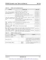
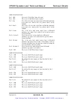
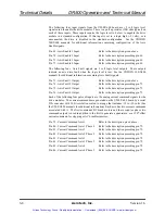
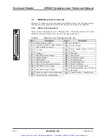
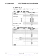
Table 3-1 defines the pinouts for the 100-pin connector that mates with J1 on the rear of
the DR500. This is a AMPLIMITE .050” series connector that is part of the 100
conductor shielded OP500 cable that connects the DR500 to connector P1 of the
UNIDEX 500/600 CPU board. The OP500 cable carries differential encoder signals as
well as analog signals which limits the maximum cable length to 15 feet.
All input and output designations are relative to the UNIDEX 500/600 CPU board,
connector P1. All connectors are N.C. (no connection) where blank.
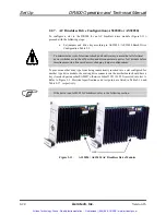
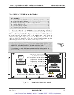
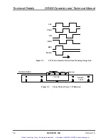
Refer to Figure 3-1 for the location of the connectors on the rear of the DR500
Chassis assembly.
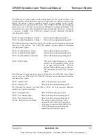
Figure 3-1.
DR500 Rear Panel Connector Layout
ENCODER 4 POWER OK
USA Service FAX: (412) 963-7000
USA: (412) 963-7470 Sales FAX: (412) 963-7459
101
Zeta Drive
World Headquarters:
Pittsburgh, PA 15238 USA
UK: 0734-
817274 FAX: 0734-815022
Deutschland: 0911-52031 FAX: 0911-5215235
AXIS 4
AXIS 3
AXIS 2
JOYSTICK 1
ENCODER 3 POWER OK
ENCODER 2 POWER OK
ENCODER 1 POWER OK
AXIS 1
1
AXIS
2 1
FROM CONTROLLER
P5 1
I/O BUS POWER OK
I/O
BUS 1
AXIS
3 1
AXIS
4 1
MISC I/
O 1
BRAKE 1
FROM CONTROLLER
P1 1
XIO cable or equivalent from Controller
100
Cond Cable to Controller
Redundant amplifier signals, ex12 VDC @
500mA
16in/
8out Digital I/O and/or Hall Effect Signals,
Digital I/O cable to
Opto 22,
PB8, PB16 or PB24 Racks
(
left) Encoder Input 3 (right) Encoder Input 4
(
left) Encoder Input 1 (right) Encoder Input 2
(
left) Joystick Interface (right) Brake Control
Emergency Stop, Interrupts, Analog I/O
Serial Tag
Indicates protective grounding connection
AXIS 1
AEROTECH
NOTE: The connectors for motor power are made with (Amp 206044-1, 206070-1, and pins 66098-7)
J10
J11
J2 J3
J4 J5
J12 J14
J13
J1
Artisan Technology Group - Quality Instrumentation ... Guaranteed | (888) 88-SOURCE | www.artisantg.com

