


DR500 Operation and Technical Manual
Introduction
Version 1.6
Aerotech, Inc.
1-5
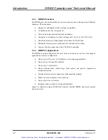
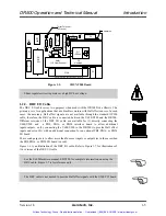
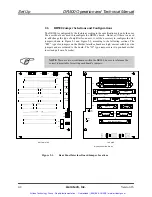
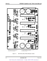
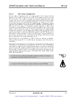
Figure 1-5.
SHUNT500 Board
Shunt regulator circuit operates at a high DC bus voltage.
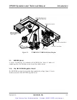
1.2.2. DRC I/O Cable
The DRC I/O cable serves two purposes when used with the DR500 Drive Chassis. The
primary use is for applications that use brushless motors with Hall effect sensors. In such
cases, the necessary Hall effect signals are not available through the standard OP500
cable, therefore, the DRC cable is connected between the U600/U500 and the DR500.
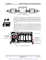
Different versions of the DRC I/O cable are available for (1) directly connecting the
U600/U500 and a PB8, PB16, or PB24 interface board to allow additional
inputs/outputs; or (2), connecting the U600/U500 to the DR500 (to provide Hall effect
inputs and extra I/O) with an additional connection for an optional PB8, PB16, or PB24
I/O board.
The second purpose is to allow more than four user inputs or outputs (as in the case when
the PB8, PB16, or PB24 I/O board is used).
Figure 1-6 is an illustration of the DRC I/O cable. Refer to Figure 1-7 for illustrations of
two versions of the DRC I/O cable.
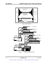
See the U600 Hardware manual, EDU154, for complete information on using the
DRC cable. Figure 1-7 is for reference only.
The DRC cable is not needed to provide Hall effect signals with the U500 PCI board.
WARNING
Turret Terminal
(2 Places)
Heatsink
1N4740
Q1
Heatsink
TP1
P1
P2
TP2
Optional Shunt BD. 690C1488 (REV -) EFN169
F1 3A
P3
TP3
R4
8K
5W
SNB1
.1, 10 Ohm Snubber
R2
20K
Q1
IRF640
C1
P4
.01UF
.47UF
6.2K
C2
R1
R5
R3
DZ1
1
TLC
2
5
1
A1
RN1
1
K
1N
914
100K
200K
D1
Artisan Technology Group - Quality Instrumentation ... Guaranteed | (888) 88-SOURCE | www.artisantg.com