


Set Up
DR500 Operation and Technical Manual
2-30
Aerotech, Inc.
Version 16
2.5.
External Device Power
The 5 volt source for the joystick, pin 19 of the Misc. I/O connector, the encoder and
limit switch power sources on the axis encoder connectors (if configured for 5 volt
operation), and pin 25 of the I/O bus connector are fused by a re-settable fuse located on
the interface board. Turning off power for approximately 30 seconds resets this fuse
(remove shorts overloads from +5V before turning power on).
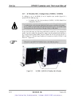
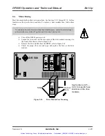
2.6. Mechanical
Installation
The DR500 Rack Mount package is designed to be mounted into a standard 19” rack. The
Desktop package can be placed on desk or bench top. Allowance must be made for the
rear panel connections and cables.
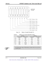
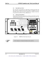
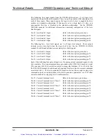
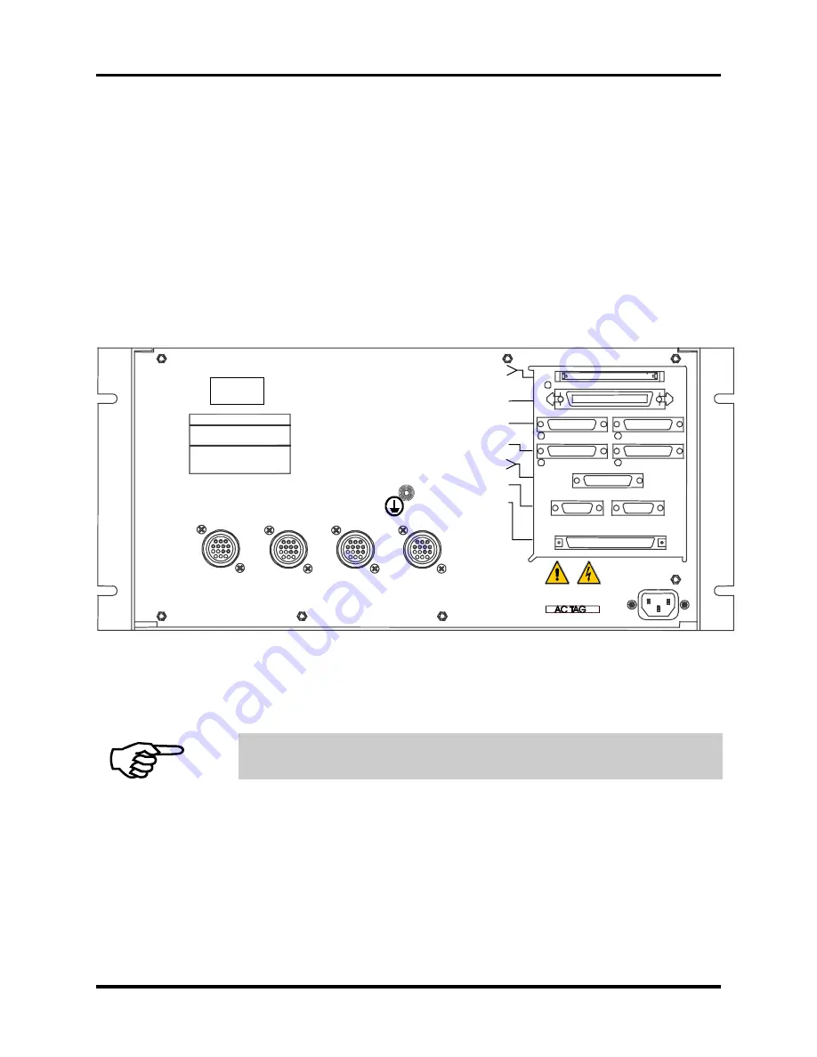
Figure 2-15.
DR500 Rear Panel Connector Layout
Refer to Chapter 3 for rack mount and desktop package dimensions.
ENCODER 4 POWER OK
USA Service FAX: (412) 963-7000
USA: (412) 963-7470 Sales FAX: (412) 963-7459
101 Zeta Drive
World Headquarters:
Pittsburgh, PA 15238 USA
UK: 0734-817274 FAX: 0734-815022
Deutschland: 0911-52031 FAX: 0911-5215235
AXIS 4
AXIS 3
AXIS 2
JOYSTICK 1
ENCODER 3 POWER OK
ENCODER 2 POWER OK
ENCODER 1 POWER OK
AXIS 1
1
AXIS 2 1
FROM CONTROLLER P5 1
I/O BUS POWER OK
I/O BUS 1
AXIS 3 1
AXIS 4 1
MISC I/O 1
BRAKE 1
FROM CONTROLLER P1 1
XIO cable or equivalent from Controller
100 Cond Cable to Controller
Redundant amplifier signals, ex12 VDC @ 500mA
16in/8out Digital I/O and/or Hall Effect Signals,
Digital I/O cable to Opto 22, PB8, PB16 or PB24 Racks
(left) Encoder Input 3 (right) Encoder Input 4
(left) Encoder Input 1 (right) Encoder Input 2
(left) Joystick Interface (right) Brake Control
Emergency Stop, Interrupts, Analog I/O
Serial Tag
W
Indicates protective grounding connection
AXIS 1
AEROTECH
NOTE: The connectors for motor power are made with (Amp 206044-1, 206070-1, and pins 66098-7)
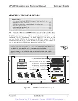
J10
J11
J2 J3
J4 J5
J12 J14
J13
J1
Artisan Technology Group - Quality Instrumentation ... Guaranteed | (888) 88-SOURCE | www.artisantg.com