


2.2.3. Stepper Motor Connections
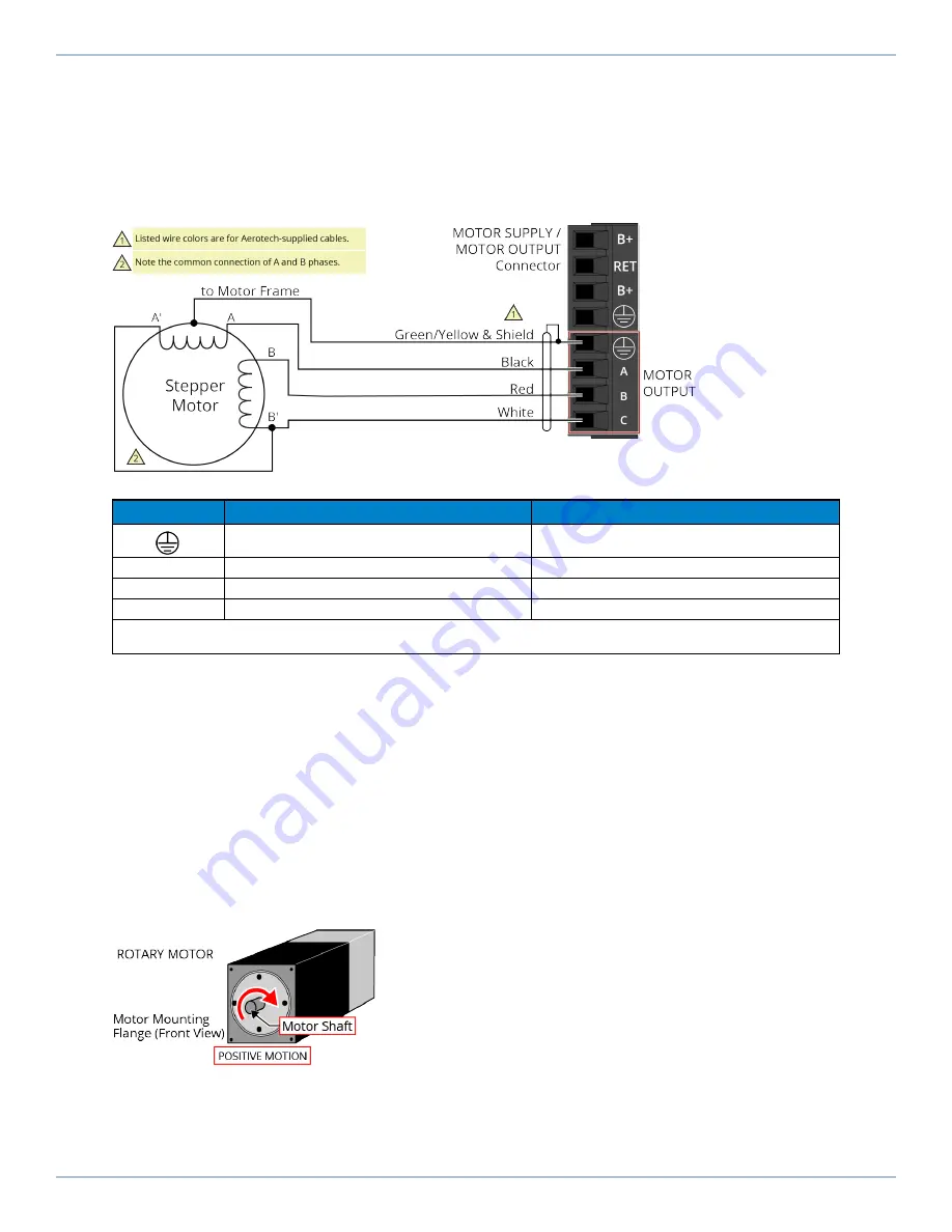
The configuration shown in
is an example of a typical stepper motor connection. Refer to
for information on motor phasing.
In this case, the effective motor voltage is half of the applied bus voltage. For example, an 80 V motor
bus supply is needed to get 40 V across the motor.
Figure 2-10:
Stepper Motor Configuration
Table 2-10:
Wire Colors for Aerotech-Supplied Stepper Motor Cables
Pin
Wire Color Set 1
(1)
Wire Color Set 2
Green/Yellow & Shield
(2)
Green/Yellow & Shield
A
Black
Brown
B
Red
Yellow
C
White
White & Red
(1) Wire Color Set #1 is the typical wire set used by Aerotech.
(2) “&” (Red & Orange) indicates two wires; “ / ” (Green/White) indicates a single wire.
2.2.3.1. Stepper Motor Phasing
A stepper motor can be run with or without an encoder.
Without an Encoder:
You do not need to phase the motor.
With an Encoder:
Because the end of travel (EOT) limit inputs are relative to motor rotation, it is
important to phase the motor.
Run a positive motion command. The motor is phased correctly if there is a positive scaling factor
(determined by the CountsPerUnit parameters) and the motor moves in a clockwise direction when
you view the motor from the front mounting flange (
). If the motor moves in a
counterclockwise direction, swap the motor leads and re-run the command. After the motor has
been phased, if you want to change the direction of positive motion, use the ReverseMotionDirection
parameter.
Figure 2-11:
Positive Motor Direction
For Aerotech-supplied systems, the motor, encoder and Hall sensors are correctly configured and
connection adjustments are not necessary.
2.2.3. Stepper Motor Connections
XL2e Hardware Manual
34
www.aerotech.com
Содержание Automation1 XL2e
Страница 1: ...Revision 1 01 Automation1 XL2e High Performance Linear Digital Drive HARDWARE MANUAL...
Страница 12: ...This page intentionally left blank Agency Approvals XL2e Hardware Manual 12 www aerotech com P E N D I N G...
Страница 22: ...1 2 2 Dimensions Figure 1 3 Dimensions 1 2 2 Dimensions XL2e Hardware Manual 22 www aerotech com...
Страница 23: ...Figure 1 4 Dimensions EB1 XL2e Hardware Manual 1 2 2 Dimensions www aerotech com 23...
Страница 71: ...Figure 3 11 Digital Outputs Schematic EB1 XL2e Hardware Manual 3 4 Digital Outputs EB1 www aerotech com 71...
Страница 82: ...This page intentionally left blank 5 2 Fuse Specifications XL2e Hardware Manual 82 www aerotech com...
Страница 86: ...This page intentionally left blank Appendix B Revision History XL2e Hardware Manual 86 www aerotech com...
Страница 92: ...Index XL2e Hardware Manual This page intentionally left blank 92 www aerotech com...


