background image


Page 8


Progressive Controller Installation 

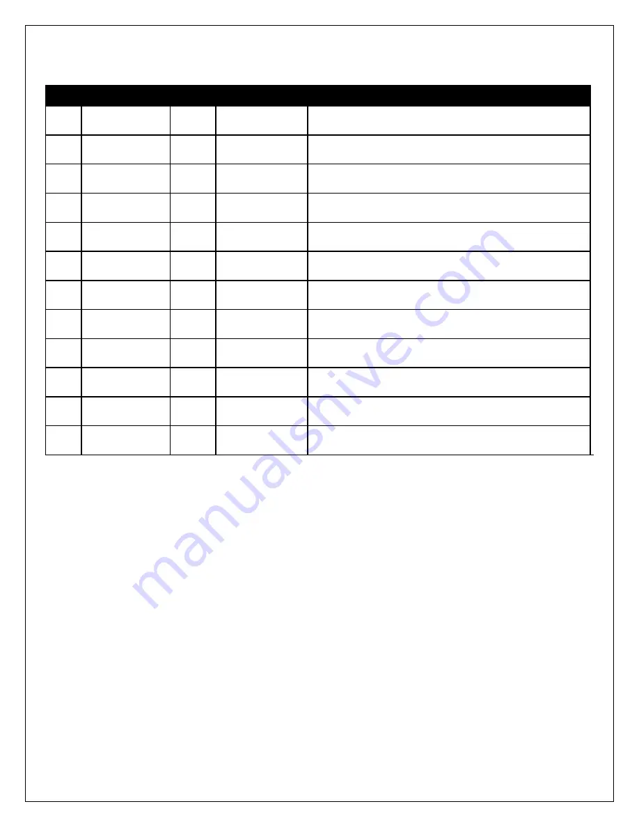
Pin # 

Description 

Wire** 

Color 

Connection 

Pump Ground 

16 

AWG 

Orange 

Connect to ground (black) wire of pump. 

LED - 

20 

AWG 

Gray 

Connect to ground (black) wire of external LED. 

LED + 

20 

AWG 

Violet 

Connect to positive (red) wire of external LED. 

Solenoid - 

20 

AWG 

Brown/White 

1.5A Low Side output.  Connect to optional flow control 
solenoid. 

Boost Safe LS 
Out 

18 

AWG 

Green 

1.7A Low Side output.  Grounded when error condition 
exists. 

Pump Power 

16 

AWG 

Pink 

Connect to the positive (red) wire of pump. 

Ground 

16 

AWG 

Black 

Main ground connection, connect directly to battery 
ground. 

Level  

20 

AWG 

White 

Connect to the white wire of the fluid tank level sensor* 

Level Switch- 

20 

AWG 

Brown 

Connect to the black wire of the fluid tank level sensor* 

10 

Arm  

20 

AWG 

Yellow 

Arms injection system.  Connect to a switched 12V 
source. 

11 

External Signal 

18 

AWG 

Blue 

Connect to External Signal. (0-5V, injector duty, MAF 
frequency) 

12 

Power 12V 

16 

AWG 

Red 

Main Power Connection, connect directly to positive 
battery terminal. 

*Note: If fluid tank is equipped with previous generation level sensor, identified by having two black wires, then 

pins 8 (white) and 9 (brown) may be connected to either of the two black sensor wires.  The polarity is 
unimportant. 

**Note: If you need to extend the wires to mount the controller use at least 16 AWG wire for the pump 

and


controller ground circuits and 18 AWG for the remainder. 

External LED Install 

Find a suitable location in the driver’s line of sight to mount the external LED.  Mount the LED 
and run the wires to the controller.  The LED indicates the operation of the controller.  If the 
pump is off and there are no errors the LED will be off.  If there are no errors and the pump is on 
the LED intensity will vary with the pump speed.  If there are any errors they will be indicated by 
flashing the LED. 

Содержание 30-3350

Страница 1: ...or vehicles used in competition which may never be used upon a public road or highway WARNING Improper installation and or adjustment of this product can result in major engine vehicle damage Use of t...

Страница 2: ...equency MAF Installation 13 Pump Tank Flush 14 Nozzle Selection and Assembly 14 Nozzle Mounting 15 Pump System Check 15 Fluid Compatibility 15 System Errors 16 Troubleshooting Diagram 17 Controller 18...

Страница 3: ...Two dial pump speed control Hardware Kit 35 4512HW Quantity Description Part 36 in 3 8 High Temp Wire Wrap 8 169 6 in Edge Protector 8 111 E 1 1 8 Tee Fitting 35 2147 10 6 Zip Tie 8 113 E 4 Bolt Hex H...

Страница 4: ...Page 4 Installation Diagram NOTE THIS KIT INCLUDES NEW STYLE INJECTOR NOZZLES THAT HAVE INTERNAL CHECK VALVES AN EXTERNAL CHECK IS NO LONGER NEEDED OR INCLUDED IN THIS KIT...

Страница 5: ...ill Tank with Water AEM recommends using Distilled Water o Turn on key power to power on controller o Use Test button on controller to flush the tank into a separate container o Drain tank and proceed...

Страница 6: ...n tank Optional 5 Gallon Tank Install Before mounting the tank check the area under the desired mounting location for fuel tanks fuel lines or any other obstructions Mount the tank in an upright level...

Страница 7: ...h in the hose at the tank and pump to install Make sure they are pushed in all the way and check with a light tug on the hose Secure the hose to the chassis using sections of the supplied hose routing...

Страница 8: ...em Connect to a switched 12V source 11 External Signal 18 AWG Blue Connect to External Signal 0 5V injector duty MAF frequency 12 Power 12V 16 AWG Red Main Power Connection connect directly to positiv...

Страница 9: ...s active low Multi Pulse Injection as is found on some diesel applications is NOT supported Please verify a single pulse for each injection event with an oscilloscope prior to operation Frequency MAF...

Страница 10: ...engine while monitoring the voltage You should observe the signal rising and falling with engine speed Please note that you may need to rev the engine high enough to put it into boost Once you have fo...

Страница 11: ...the other will be the desired signal wire from the ECU Using a voltmeter you can determine if you have the correct signal by watching the voltage as the engine is running As duty cycle increases and m...

Страница 12: ...y To determine if you do in fact have the correct wire you can try and rev the engine while monitoring the voltage If the signal rises and falls with the engine speed then you have likely identified t...

Страница 13: ...ecause the signal has a duty cycle of 50 and a voltage range of 0 5V so the average voltage will be about To determine if you do in fact have the correct wire you can try and rev the engine while moni...

Страница 14: ...C Fuel Flow F I 7 BSFC W M Flow N A W M Flow 5 10psi Boost W M Flow 10 25psi Boost W M Flow 25 psi Boost 150 788 1101 95 220 275 330 200 1050 1469 126 294 367 441 250 1313 1836 158 367 459 551 300 157...

Страница 15: ...terior of the intake once the nozzle is fully installed Pump System Check The TEST push button on the controller module can be used to test the system Press and hold the button to activate the pump Th...

Страница 16: ...Pump will continue to run Refill fluid reservoir 2 Pump Open Circuit An open circuit has been detected in the circuit wiring that drives the pump BoostSafe Enabled Pump will NOT continue to run Check...

Страница 17: ...Page 17 Troubleshooting Diagram...

Страница 18: ...Start dial has a range from 0 full counterclockwise rotation to 100 full clockwise rotation The Full dial has a range of 0 full counterclockwise rotation to 100 full clockwise rotation It is suggeste...

Страница 19: ...on available One can detect a short at any time but produces a slight buzzing in the pump This should not be noticeable under most conditions but can be turned off if it is objectionable If turned off...

Страница 20: ...ow since it has passed both the start and the full requirements Engine Tuning Water methanol injection is generally not considered a bolt on power adder for forced induction gasoline applications Engi...

Страница 21: ...ines and push to connect fittings is very unsafe The performance advantages of using greater than 50 methanol concentrations are small if they exist at all However the safety issues are very real and...

Страница 22: ...needle type gauge that allows you to accurately monitor the status of your injection system in real time Available in max flow rates of 500 cc min or 1000 cc min with a black or white face The AEM wa...

Страница 23: ...orized repairs or alterations voids this warranty AEM disclaims any liability for consequential damages due to breach of any written or implied warranty on all products manufactured by AEM Warranty re...

Отзывы: