--------------------------------------------------------------------------------16/20--------------------------------------------------------------------------------
VER<CR> -> version query of the ARE i2
MP3<CR> -> switching to antenna channel 3
GT<CR>
-> reading the transponder in the field of antenna 3
MP4<CR> -> switching to antenna channel 4
GT<CR>
-> reading the transponder in the field of antenna 4
5.3
Controlling via digital inputs (mode 3)
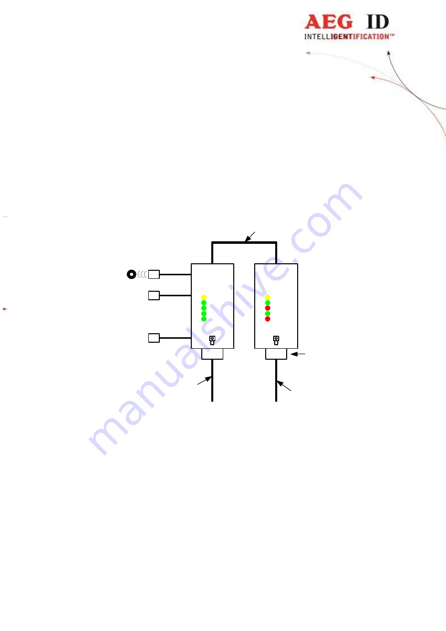
Figure 5: system overview controlling via digital inputs (mode 3)
In mode 3 the power supply of the AMP 4/8 and the ARE i2 are seperatly. The switching of the channels
is done binary via the digital inputs. The inputs are low-activ, that means that you have to pull them to
ground to get a logical ‘1’ (see figure 6).
antenna 1
antenna 2
antenna connection
power supply
+
4 data lines for the digital inputs
RS232/USB
+
power supply (e.g.
PC connection cable)
.
.
.
antenna 8
Vcc
1
2
4
8
AEG
ID
AMP 4/8
L1
L2
L3
L4
L5
AEG
ID
ARE i2
SAB-cap


