


- Programmable Relay I/O Card ..................................................... 3-17
- ModBUS Card .............................................................................. 3-18
3-3-6 Additional Options ............................................................................ 3-19
3-4 Technical Specification ................................................................................ 3-20
4.
Installation .......................................................................................................... 4-1
4-1 Before Installation........................................................................................ 4-1
4-2 Package Inspection ..................................................................................... 4-1
4-3 Storing Conditions before Installation .......................................................... 4-2
4-4 Unpacking Procedure.................................................................................. 4-3
4-4-1 Protect 3.M 2.0 80 kVA .................................................................... 4-3
4-4-2 Protect 3.M 2.0 120 kVA .................................................................. 4-4
4-5 Installation Environment .............................................................................. 4-5
4-5-1 Handling Safety................................................................................ 4-5
4-5-2 UPS Positioning ............................................................................... 4-5
4-5-3 Environment ..................................................................................... 4-7
4-6 Wiring .......................................................................................................... 4-8
4-6-1 Preparations..................................................................................... 4-8
4-6-2 Wiring (Single Unit) .......................................................................... 4-10
4-6-3 Connecting External Battery Cabinet ............................................... 4-12
4-6-4 Wiring (Parallel Redundancy, Single Input) ...................................... 4-13
4-6-5 Wiring (Parallel Redundancy, Dual Input) ........................................ 4-14
5.
Operating
Procedure....................................................................................... 5-1
5-1 Startup Procedure (Single) .......................................................................... 5-1
5-2 Battery Startup Procedures (Single) ............................................................ 5-2
5-3 Shutdown Procedure (Single)...................................................................... 5-2
5-4 Manual Bypass Startup (Single) .................................................................. 5-3
5-5 Startup Procedure (Parallel Redundancy) ................................................... 5-4
5-6 Shutdown Procedure (Parallel Redundancy) .............................................. 5-4
5-7 Manual Bypass Startup (Parallel Redundancy) ........................................... 5-6
6. Power Module Replacement ............................................................................ 6-1
6-1 Power Module LED Indication ..................................................................... 6-1
6-2 Power Module Replacement ....................................................................... 6-2
7. Display and Configuration ............................................................................... 7-1
Содержание 80 / 120 kVA
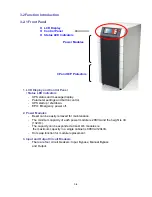
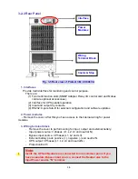
Страница 14: ...3 1 3 General View 3 1 Appearance LCD Display and Control Panel ...
Страница 15: ...3 2 3 1 1 Dimensions 80kVA Fig 3 1 Power Unit 80kVA Fig 3 2 External Battery Pack 80 kVA cabinet size ...
Страница 16: ...3 3 3 1 2 Dimensions 120kVA Fig 3 3 Power Unit 120 kVA Fig 3 4 External Battery Pack 120 kVA cabinet size ...
Страница 36: ...4 3 4 4 Unpacking Procedures 4 4 1 Protect 3 M 2 0 80 kVA ...
Страница 37: ...4 4 4 4 2 Protect 3 M 2 0 120 kVA ...
Страница 57: ...6 3 Fail On Off Fail On Off ...


