background image

AEE

 Quad-rotor Aircraft System 

Professional

·

Leading


- 10 - 

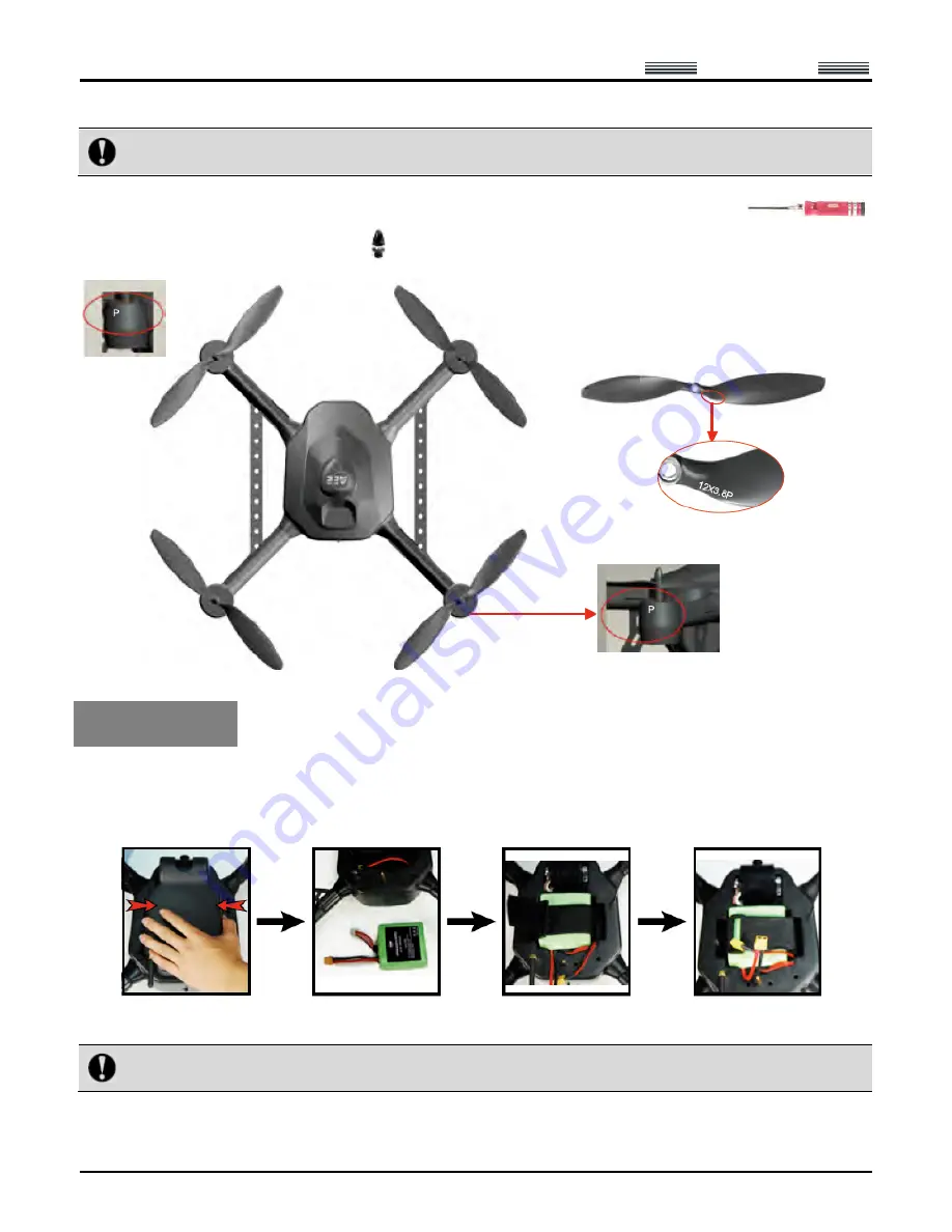
counter-clockwise propeller which should be installed on a support arm with “P”.     


Wrong installation of clockwise and counter-clockwise propellers will inevitably result in errors in the aircraft 
lift system, further leading to unpredictable consequences.   

 
Place the propeller blades and propeller holders on corresponding motor shafts; use the wrench (

to clockwise tighten the propeller holders (

).   


Install Battery 


1. First remove the protective cover at the bottom of the aircraft: 1) pull off the latch; 2) squeeze the two sides of the 

cover to remove the protective cover.   

2. Take the battery out of the packing box, install it in the battery case at the bottom of the aircraft, and tighten it with 

a fixing strap.   


3. After it is confirmed that the battery has been properly installed, connect it to the power interface to power up, 

install the protective cover, and lock the latch.   


Notice:  Please  make  sure  the  power  switch  of  the  aircraft  is  in  the  OFF  state  during  installation  of  the 
battery. 

 
4. After completion of the above three steps, place the aircraft on the ground (a flat ground is recommended); then 

A propeller with “P” should be installed on a 

support arm with “P”.   

Содержание F50 A

Страница 1: ...Aircraft Aircraft System Professional Leading User s Manual Please read this Manual carefully before use and keep it handy for future reference Unprecedented Technology...

Страница 2: ...f Buttons 12 Preparations for the Remote Control 14 Set Parameters on the Screen of the Remote Control 15 Start the Aircraft 22 Direction Control 22 Go Home and Shut down the Aircraft 25 Control the F...

Страница 3: ...e that the video and radio antennas have been properly installed to avoid influence on the aircraft and the video receiving distance or damage to the transmitter module inside the remote control Witho...

Страница 4: ...age of map files please timely back up the map data after downloading Please disable the function of auto clearing Internet Explorer in different types of antivirus software to prevent the map data fr...

Страница 5: ...ironment at room temperature 3 Put the battery on a nonflammable utensil such as ceramic plate for charging Specification of the Charger Specification Parameter Specification Parameter AC input 100 24...

Страница 6: ...then remove it Step 2 Disconnect the power plug Step 3 Loosen the tie and take out the battery Take out the battery of the remote control Step Illustration Description Step 1 Rotate to open the batte...

Страница 7: ...d then you can set the parameters of the charger 3 Set Parameters and Start Charging After the battery is connected to the charger set the parameters for the charger as follows Battery Battery capacit...

Страница 8: ...f the battery press for confirmation after the voltage is adjusted to the proper value 5 After setting all parameters long press for 2s and the charger begins to detect the battery after successful de...

Страница 9: ...not charge the battery in reverse polarity or over discharge it 9 Do not connect the battery in reverse polarity 10 Any waste battery should be recycled in an environment friendly way 11 If the batter...

Страница 10: ...c Wrench 1pc Adaptor of ground control station 1pc High gain dual band directional antenna 1pc including 2 feeder lines and 1 tripod Vehicle mounted charger clamp cable for ground station optional 1pc...

Страница 11: ...ed conveniently during the flight and real time control of air route and mission of the aircraft can be realized Guide for Components of the Aircraft Install Propellers There are two clockwise propell...

Страница 12: ...bottom of the aircraft 1 pull off the latch 2 squeeze the two sides of the cover to remove the protective cover 2 Take the battery out of the packing box install it in the battery case at the bottom...

Страница 13: ...off the power switch after the aircraft is placed at the take off position to ensure safety there should be no obstacle within the radius of 5 10m around the take off position 7 Turn on the power swi...

Страница 14: ...rborne recording stop button Power switch Zoom in button Roll fine adjustment button Pitch up down roll left right joystick PTZ control button Manual automatic flight switch USB port Local recording i...

Страница 15: ...ution modes 1080p 25f 960 25f and 720p 25f Stop recording The airborne camera stops recording when it is pressed once Menu Press M to enter the main menu of remote control Long press M for 5 seconds t...

Страница 16: ...them Radio antenna corresponds to L Radio Video antenna corresponds to R Video Notice Please make sure that the video and radio antennas have been properly installed to avoid influence on the flight a...

Страница 17: ...f the remote control 2 Touch Servo Checking to enter the setting interface Indication of airborne recording status Heading Indicator Indication of local recording status of remote control Indication o...

Страница 18: ...AEE Quad rotor Aircraft System Professional Leading 16...

Страница 19: ...the interface of Servo Checking in the above step turn the left and right joysticks for 5 10 circles by 360 to enter the state of joystick calibration indication bars of roll pitch throttle and cours...

Страница 20: ...e visual angle Narrow visual angle the following is an example of an image under different visual angles in the preview mode The above optional visual angles can be selected according to your preferen...

Страница 21: ...Continuous capture three In this mode the system will take three photos continuously when Shutter is pressed once 3 Automatic continuous shooting mode The time interval of automatic continuous shootin...

Страница 22: ...mory space of the camera is more than 200M 2 Light Metering Mode Average metering use this mode when the luminance difference between the photograph subject and the background is relatively slight and...

Страница 23: ...onth Day Hour and Minute c Touch Save to complete setting Notice When Time Indication on Image is ON after Save is pressed to complete setting date and time will be indicated at the bottom right corne...

Страница 24: ...than or equal to 6 Start the aircraft in the following way Simultaneously turn the left and right joysticks to the directions shown below Turn the left joystick to the bottom left corner Turn the righ...

Страница 25: ...imbing speed increases with the joystick turning angle Turn the left joystick backwards and keep the right joystick in the original position Go downwards The motor speed and the propeller speed decrea...

Страница 26: ...s needed to slightly push forward the throttle to adjust the flight altitude so as to realize horizontal flight of the aircraft Turn the right joystick rightwards and keep the left joystick in the ori...

Страница 27: ...the go home mode to return and land at the take off position Notice In the manual flight mode 10s after the aircraft receives and executes the go home command you can turn the automatic manual flight...

Страница 28: ...uch information as battery level speed altitude longitude and latitude Automatic control of take off and landing With the joystick control function manual flight can be realized Air routes can be set...

Страница 29: ...roll and pitch 10 Network interface Connect to external network 11 USB Connect to external USB device 12 Wiring sealing plug Protect the connecting wires 13 Auto manual fly switch Switch between manu...

Страница 30: ...o communication antenna on the right side clockwise rotate and fix the antennas after they are aligned with the corresponding interface For short distance operation it is suggested the metal antenna s...

Страница 31: ...hen press the Start Main Unit Button to start the ground control station Notice The default system is Microsoft Windows XP Professional on dev sdal Introduction to Main Interfaces of the Ground Statio...

Страница 32: ...e settings corresponding to the content displayed in the interface Toolbar Show or hide the toolbar Instruments Display Bar Show or hide the instruments display bar Mission Editor Show or hide the mis...

Страница 33: ...ected 5 Help Menu 6 Toolbar Connect or close serial ports load mission save mission display track etc 7 Video Management Window Please see the section of Functions of Video Management Window in Ground...

Страница 34: ...altitude speed and hold time Click Edit Waypoint to reedit the mission that has been edited Click Finish Editing to confirm the current mission the color of air route changes to green To add a waypoin...

Страница 35: ...llows Start the ground station software Switch to the Manual Fly mode Power up the aircraft to receive satellite signals Connect serial ports and send joystick data Check before take off Start up the...

Страница 36: ...ircraft Perform auto take off or manual take off Perform Auto Fly or Fly To to a designated waypoint Go home abort mission and go home Landing 1 Start the Ground Station GS Software Hereinafter Referr...

Страница 37: ...through Menu Tool Joystick Data Select serial port COM2 and click Connect to connect the joysticks which are used to control the aircraft Check Send joystick data the progress bars will have correspon...

Страница 38: ...to control the aircraft please make sure that the remote control is in the OFF state before take off 3 For joystick calibration please uncheck Send joystick data to avoid unpredictable consequences ca...

Страница 39: ...o add a waypoint on the map to add a waypoint Method 2 Click Add Waypoint in the Flight Mission Editor and then click the position where you want to add a waypoint on the map to add a waypoint It is b...

Страница 40: ...to the corresponding position Change altitude speed and hold time of waypoint Input the desired figures in the corresponding attribute values to change the altitude speed and hold time of the waypoin...

Страница 41: ...flight mission according to the following steps Step 1 You can save the currently edited flight mission through Menu File Save Mission or the button on the Taskbar The following dialog box will pop u...

Страница 42: ...ee the description in the section of Start the Aircraft with the Remote Control 1 During outdoor flight please make sure that the GPS signal strength indicator is no less than 6 2 Check if the indicat...

Страница 43: ...and the aircraft will fly to this waypoint after reaching this waypoint the aircraft will hover Only one target waypoint can be added every time 3 Edit Flight Mission in the Air You can continue to e...

Страница 44: ...Video Management Window Function of the Ground Station Software The aircraft starts automatic video recording after startup enter the tab of Video Management Window of the ground station then click Pr...

Страница 45: ...g of the airborne camera during recording the button will remain selected click the button again to stop recording and it will bounce up 5 Airborne Photo shooting Support Snapshot Click Airborne Photo...

Страница 46: ...e 8 Camera Setting TV out Format Only PAL can be selected Metering Mode Average metering use this mode when the luminance difference between the photograph subject and the background is relatively sli...

Страница 47: ...gs Time Setting Set the system time Loop Recording When Loop Recording is ON recording is saved as a segment file by each 10 min if the space of the memory card is not enough the first recording file...

Страница 48: ...s provided in the Ubuntu operating system This software provides the following three functions 1 Save map data during use of the ground station the user can save the map data according to area partiti...

Страница 49: ...Then go back to the Ubuntu system to open the Google Maps Data Management software Click Data Backup fill in the backup name and click OK to save the last map data browsed in the ground station softwa...

Страница 50: ...fter startup the aircraft will automatically enter the recording state The user can preview the video on the screens of the remote control and the ground station When the aircraft is shut down recordi...

Страница 51: ...ght accident may be caused by low battery of the aircraft and remote control Specification Description Specification Flight mode Manual remote control autonomous hover autonomous route No load take of...

Страница 52: ...properly as required 2 Check the power batteries of the aircraft to make sure the battery level is high enough Protection Mechanism 1 During flying in the manual mode when it is beyond the operating r...

Страница 53: ...Please read this Manual carefully before use and keep it handy for future reference National Hi tech Enterprise Patented Technologies Popular in European American and Asian Markets...

Страница 54: ...Created in China Made in Shenzhen Add 14F Microprofit Mansion No 6 Gaoxinnan 6th Road South Area of High tech Park Nanshan District Shenzhen Tel 0755 29518908 Fax 0755 27358999...

Отзывы: