background image

----------

l�-'

un 

Jet 

_________

__

AEC IST

9

 (

1


0

-20 кВА)

 - 

руководство по эксплуатации

. Юниджет

Постоянная ссылка на страницу: 

https://www.uni-jet.com/catalog/ibp/on-line-

ibp/aec-ist

9

/

Содержание IST9

Страница 1: ...l un I Jet _________ __ AEC IST9 1 0 20 https www uni jet com catalog ibp on line ibp aec ist9...

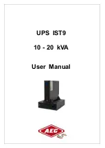
Страница 2: ...UPS IST9 10 20 kVA User Manual...

Страница 3: ......

Страница 4: ...he actual product Suitable Model 10kVA 15kVA 20kVA 30kVA 40kVA Symbol Conventions The manual quotes the safety symbols these symbols used to prompt users to comply with safety matters during installat...

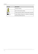
Страница 5: ...escription Anti static prompting Be care electric shock prompting Provides a tip that may help you solve a problem or save time Provides additional information to emphasize or supplement important poi...

Страница 6: ...nvironment Requirements 3 2 Overview 5 2 1 Product Intro 5 2 1 1 Features 5 2 1 2 Appearance 6 2 1 3 Fittings Illustration 9 2 2 Work Principle 12 2 2 1 Work Principle Diagram 12 2 2 2 Work Mode 13 2...

Страница 7: ...ring Between UPS and Distribution Module of 10kVA 20kVA UPS 37 3 4 7 Wiring Between UPS and Distribution Module of 30kVA 40kVA UPS 39 3 4 8 Wiring of Parallel System 42 4 Screen Operation 48 4 1 Menu...

Страница 8: ...New UPS into Parallel System Online 62 5 4 5 Redundance Function of Parallel System 63 5 5 Periodic Preventative Maintenance 63 5 6 Battery Maintenance 63 5 7 Troubleshooting 64 5 7 1 Common Fault 64...

Страница 9: ......

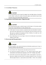
Страница 10: ...please read the announcements and operation instructions in this section carefully to avoid accident The DANGER WARNING CAUTION etc in the manual are not all the safety announcements that you must abi...

Страница 11: ...e tools with insulated handle Don t put tools or other conductive objects on the battery It is prohibited to short the positive pole and negative pole of the battery or connect them reversely which is...

Страница 12: ...until it is powered off completely 10min Otherwise the output may exist electricity which may cause electric shock When dismantling fan do not put fingers or tools into the rotating fan to avoid devic...

Страница 13: ...inside UPS which will reduce the service life of inner components and even affect the life span of the UPS The UPS must be used below 2000m If the altitude exceeds 2000m it needs to decrease the rate...

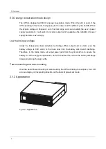
Страница 14: ...and three out mode UPS three in and one out mode UPS one in and one out mode UPS 30kVA 40kVA UPS support three in and three out mode UPS three in and one out mode UPS The UPS can monitor the grid freq...

Страница 15: ...w mains input voltage Adopt the independent rapid detection technology When output load is small even the battery voltage is 80V which is the main slow limit the battery still doesn t discharge Theref...

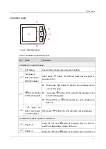
Страница 16: ...tton and breathing light Short press button to confirm the command of the current LCD page Long press button for 3s will entry the parameter and function setting page When UPS is on button will be in...

Страница 17: ...For the detail of the wiring terminal of each mode please see 3 4 1 Wiring Operation 2 The intelligent slot is optional Built in SNMP card RS485 dry contact card and communication protocol transfer ca...

Страница 18: ...power supply and at the same time the LCD shows BMD fault Once the port recovers short connection the fault will be removed automatically If the EPO port is disconnected the UPS will shut down all in...

Страница 19: ...bar 4 3PIN copper bar The installation position of the UPS main and power distribution module is as shown inFigure2 5 Figure2 6 Figure2 5 Installation 33 mode copper bar position of 10kVA 20kVA UPS Fi...

Страница 20: ...The copper bar for short connect with the three phase bypass input terminal and three phase output terminal only for 31 mode UPS Table2 3 Copper bar illustration Copper bar No Illustration Sketch map...

Страница 21: ...rter charger bypass static switch etc function module the input power includes mains input bypass input battery input the output mode includes inverter output bypass output and maintenance bypass outp...

Страница 22: ...ode ECO power supply mode and maintenance bypass power supply mode The maintenance bypass power supply mode can only suitable for install the UPS series fitting with distribution module Normal mains p...

Страница 23: ...outage completely the UPS will shut down about 1min later automatically and close the power of the UPS to avoid the battery discharge slimly thus to protect the service life of battery Once the mains...

Страница 24: ...energy consumption At the ECO mode the UPS efficiency can be 99 Maintenance bypass power supply mode suitable for the system with distribution module When the UPS needs to be maintained and the power...

Страница 25: ...uip distribution module or battery box according to needs 2 3 1 Distribution Module Appearance Figure2 14 Appearance of distribution module Front panel of 10kVA 20kVA The operation breakers of distrib...

Страница 26: ...sert the buttons at right side into the body and then insert the buttons at left side into the body Figure2 16 Distribution module illustration dismantle front panel of 10kVA 20kVA UPS Rear panel of 1...

Страница 27: ...atus pop up automatically the UPS close the inverter and turn to bypass to supply power then close the maintenance bypass breaker turn off the AC input breaker bypass breaker and AC output breaker at...

Страница 28: ...iew 19 Rear panel of 30kVA 40kVA Figure2 20 Distribution module rear panel of 30kVA 40kVA UPS 2 3 2 Battery Box Appearance Figure2 21 Appearance of battery box Rear panel Figure2 22 Rear panel of batt...

Страница 29: ...3 1 Unpacking and Checking Unpack and check the UPS according to follows Inspect the appearance for shipping damage If any shipping damage is found report it to the carrier immediately Check the deliv...

Страница 30: ...max steady state phase current of each work mode Table3 2 shows the rated current of recommended breakers Table3 3 shows the min recommended wire cross sectional area Select the wires and breakers ac...

Страница 31: ...5 to 2 times of UPS input max current and cannot with leakage protection which is to avoid wrong action of breaker The distribution box should be manufactured by professional company The breaker of D...

Страница 32: ...the three wires Please notes that when the UPS is single phase input the three fire wires need to be connected to the same phase of power input When 30kVA 40kVA UPS is set to 31 mode bypass input and...

Страница 33: ...lel AC output neutral wire N 10 1 16 2 parallel 16 1 25 2 parallel DC input BATN 16 3 16 3 25 3 25 3 Grounding wire PE 16 1 16 1 16 1 25 1 Table3 5 Contrast list between wires and wiring terminals Wir...

Страница 34: ...7 2 6 7 7 2 9 0 7 2 9 0 30kVA 40kVA UPS Wiring terminal dimensions of the wiring terminals of 30kVA 40kVA UPS recommend type as shown in Figure3 2 If users have additional terminals required please c...

Страница 35: ...12 2 15 4 B 6 15 8 3 C 8 4 D 11 5 13 3 The equipped wires by our company are all passed the national standard or UL certification the quality is perfect and meets the requirements of safety standard T...

Страница 36: ...the UPS onto the assembled support base as shown in Figure3 5 Figure3 5 Install the UPS End Install the UPS with battery box or distribution module When equip battery box or distribution module the in...

Страница 37: ...the assemble way is the same Step 2 Put the UPS and distribution module onto the assembled support base as shown in Figure3 7 Figure3 7 Install the UPS and distribution module Step 3 Take out the com...

Страница 38: ...y box it needs to install another 2 combination parts End 3 3 2 Rack mounting UPS and the optional also can be installed in 19 inch standard cabinet to use The rack mounting procedure of UPS battery b...

Страница 39: ...dismantled front during transporting do not make it bear any force The device needs to be transported by two or more people Step 2 Push the UPS into the cabinet and fasten it by screws as shown in Fi...

Страница 40: ...he power wire at the place where is easy to be trod or tripped If there is an optional distribution module the wiring of UPS and distribution module optional shall be connected with the distribution m...

Страница 41: ...g of 10kVA 20kVA UPS 3 4 2 Wiring Operation of 30kVA 40kVA UPS 33 mode The input and output wiring of 33mode UPS is as shown in Figure3 13 The output and input have two N terminal bar respectively and...

Страница 42: ...of copper bar 1 connect them to the wiring terminal of UPS The wiring diagram of 31 mode UPS is as shown inFigure3 14 When the wire output and the input N wire are in parallel of two cables the two gr...

Страница 43: ...istribution module installed in the top layer for easy cable connection and operation Tower mounting products the distribution module is installed on the left side of UPS to facilitate cable connectio...

Страница 44: ...allation 35 Figure3 16 Wiring diagram between UPS and two parallel connected battery boxes Figure3 17 Wiring diagram between UPS and two sets parallel connected battery boxes each set has two battery...

Страница 45: ...x of 30kVA 40kVA UPS The wiring of parallel connected battery box and each mode UPS is the same in this section we take 40kVA as an example to illustrate Figure3 18 Wiring diagram between UPS and two...

Страница 46: ...binet has 32 cells and one 3P breaker the external wiring includes BATT BATT and battery neutral wire The selection of battery wires and breaker specification please see Table3 2 Table3 3 and Table3 4...

Страница 47: ...VA UPS 31 mode The copper bar from Table2 2 are short connect with 3P terminal bar of the bypass and output The supporting UPS and the distribution wire are connected one to one according to the wire...

Страница 48: ...UPS and distribution module is shown in Figure3 22andFigure3 23 33 mode The supporting UPS and the distribution wire are connected one to one according to the wire information Figure3 22 Wiring Betwee...

Страница 49: ...ction plate to the device the installation procedure is as follows Install wiring plates The wiring covers install procedure of each mode UPS and distribution module is the same in this section we tak...

Страница 50: ...ve the protective cover Step 3 Connect the wires in accordance with3 4 1 Wiring Operation as shown in Figure3 26 Figure3 26 Connect the wires Step 4 Reinstall the wiring row cover in the corresponding...

Страница 51: ...ad screws End 3 4 8 Wiring of Parallel System Step 1 Install the battery and UPS of parallel system separately according to 3 3 Mechanical Installation Step 2 Connect the wires of input output battery...

Страница 52: ...3 Installation 43 Figure3 29 Diagram of 33 mode parallel system wiring of 10kVA 20kVA UPS...

Страница 53: ...3 Installation 44 Figure3 30 Diagram of 31 mode parallel system wiring of 10kVA 20kVA UPS 30kVA 40kVA...

Страница 54: ...3 Installation 45 Figure3 31 Diagram of 33 mode parallel system wiring of 30kVA 40kVA UPS...

Страница 55: ...6 Figure3 32 Diagram of 31 mode parallel system wiring of 30kVA 40kVA UPS Step 3 Connect the parallel port of each unit in parallel by parallel wires as shown in Figure3 33 Figure3 33 Wiring diagram o...

Страница 56: ...trictly which is to ensure the bypass power of parallel system is the same phase 2 The parallel system of this series UPS can share battery groups but the battery amount of each UPS must be the same 3...

Страница 57: ...d system settings of UPS screen 4 1 Menu Hierarchy The menu hierarchy of the screen is as shown in Figure4 1 Figure4 1 Menu hierarchy of the screen The parameter values and other details in the pictur...

Страница 58: ...the password correctly before continuing to use it Please contact the local customer service report the machine serial number on the LCD you can get the boot password After entering the password pres...

Страница 59: ...the current battery status and battery voltage System current date display System current operating status display Monitor page number display The working state and energy flow on the main interface...

Страница 60: ...4 Screen Operation 51 Figure4 4 Main power Inverter Output Figure4 5 Battery Inverter Output Figure4 6 ECO Bypass output Figure4 7 Maintenance bypass output...

Страница 61: ...page number and page loop order 4 6 Setting Page On the monitoring page by long pressing function button for 3s you can go to the settings page And the setting page structure diagram as shown in Figu...

Страница 62: ...t five items as shown in Figure4 10 Each item has a hollow box icon before it and if the item is selected the hollow box icon becomes a solid box icon You can select page content by pressing the up do...

Страница 63: ...page which is a second class page mainly for the directory display function the page display includes bypass parameter settings battery parameter settings and output parameter setting three as shown i...

Страница 64: ...u can set the section number minus plus by pressing the up down page turning button When the section number is adjusted to the value to be set the section number setting can be completed by the short...

Страница 65: ...be performed for the standard test and after adjusting to the specific option the standard test can be completed by short pressing the function button Because the current three battery tests cannot b...

Страница 66: ...of the selected option becomes a solid box When you select the back button in the lower right corner the back button is displayed as a opposite color state at which point the short press function but...

Страница 67: ...ite color state at this time short press function button can enter the page to the previews level of the page the password input page on the previews level of the page for the settings management page...

Страница 68: ...peration you can set the trial function and the trial time the setting method is the same as the other settings mentioned above and it is not repeated here 1 The permission set is a restricted operati...

Страница 69: ...port is correct If it is long backup model check if the wiring between UPS and battery box is correct and reliable Check if the wiring is neat and the wire binding is in accordance with the specifica...

Страница 70: ...ollowing steps for start the parallel system Step 1 Ensure that each unit of parallel system is installed properly start each unit of parallel system according to the 5 2 Startup Operation one by one...

Страница 71: ...5 4 3 Exit Parallel System Online When one UPS in parallel system fault it will exit from parallel system automatically with sound light alarm At that time perform the operations shown in Figure5 1 th...

Страница 72: ...form the following maintenance regularly Clean the UPS by dry cloth regularly Don t use liquid or spray cleaner Before cleaning shut down the UPS Check if the wiring of input and output is firmly and...

Страница 73: ...e5 1 Troubleshooting Fault phenomenon Possible reason The mains normal after starting the UPS it outputs normally but it works in the battery mode and the buzzer beeps intermittently 1 Check if the co...

Страница 74: ...f UPS is beyond the allowable range Usually UPS works normally When power failure it doesn t transfer to battery mode or it transfers to battery mode and battery under voltage protection soon 1 Batter...

Страница 75: ...t match the actual system 7 Frequency Long beep The UPS of the frequency in the parallel does not match the actual system 8 Bypass Long beep The UPS of the bypass voltage or frequency in the parallel...

Страница 76: ...larm cannot be restored please report repair promptly 20 No Redund Slow beep alarm once about every 2 0s The total output load of the UPS parallel system exceeds the full load of the single machine ch...

Страница 77: ...attery wiring fault charging short under voltage protection under voltage warning problem please check the battery wiring and the current state is normal No buzzer warning The battery charging tempera...

Страница 78: ...not allowed to shipping with the device While midway transportation do not put the device in the open air The device cannot suffer any rain snow or liquid material or mechanical damage 6 3 Storage Du...

Страница 79: ...176 280 the UPS can bear load of 100 rated power When the input voltage in the range of 80 176 the output of the UPS needs to decrease rated power linearly to use Frequency range Hz 40 70 Bypass sync...

Страница 80: ...e set to 1W N PE Capacity kVA kW 10 9 15 13 5 20 18 30 27 40 36 Voltage Vac L N 220 230 240 default is 220 L L 380 400 415 default is 380 Frequency Hz When mains normal it tracks the bypass input freq...

Страница 81: ...485 Alarm function Alarm for battery low voltage mains abnormal UPS fault output overload etc Protection function Protection for battery under voltage overload short circuit over temperature input ove...

Страница 82: ......
Отзывы: