


96-8006123_11-03-2021
Information subject to change
25
8302 OPERATOR’S MANUAL – SECTION 6
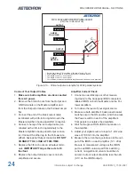
2.
Connect the black (ground) output cable to the
ground terminal of your load.
3.
Connect “Y” end of the red (positive) output
cable to the positive terminal of your load.
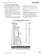
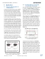
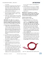
Refer to
Figure 6.11
for completed system wiring.
6.4.3
Push/Pull Multi-amp Configuration
To configure and connect two amplifiers for opera
-
tion in a Push/Pull (series) configuration, begin by
designating one amplifier as the Master amplifier,
and the other amplifier as a Follower amplifier.
Consider placing a “Master” or “Follower” label on
each amplifier’s back panel to clarify the amplifier
designation during setup and operation.
IMPORTANT: Make sure both amplifiers are
disconnected from AC power.
7. If no significant current is observed in either
amplifier, continue with the system setup.
IMPORTANT: If current exceeds 2A (0.1V)
from either amplifier, DO NOT complete the
system setup. Contact AE Techron Techni-
cal Support for assistance.
8. Slowly raise the input voltage from 100 mV to
to 2.5V while continuing to monitor current at
IMON.
IMPORTANT: If current exceeds 2A
(0.1V) from either amplifier at any time, DO
NOT complete the system setup. Contact AE
Techron Technical Support for assistance.
Connect the Load
1.
Make sure both amplifiers are disconnected
from AC power.
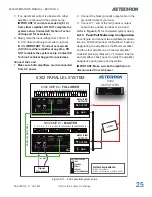
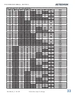
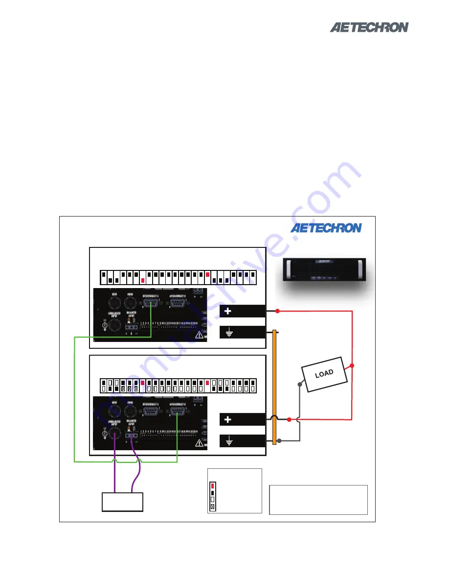
Figure 6.11 – 8302 parallel system setup
8302 PARALLEL SYSTEM
PARALLEL
DB9 CABLE
8302 AMP #1 -
MASTER
and/or
Signal
Generator
8302
AMPLIFIERS
SYSTEM REQUIREMENTS:
(2) 8302 amplifiers
(1) 8302 Multi-amp Kit (69-8005462)
8302 AMP #2 -
FOLLOWER
AMPLIFIER
OUTPUTS
OUTPUT
GND
AMPLIFIER
OUTPUTS
OUTPUT
GND
KEY FOR DIP SWITCH
SETTINGS:
REQUIRED
DEFAULT
OPTIONAL
NOT RECOMMENDED
1 2 3 4 5 6 7 8 9 10 11 12 13 14 15 16 17 18 19 20 21 22 23 24
1 2 3 4 5 6 7 8 9 10 11 12 13 14 15 16 17 18 19 20 21 22 23 24
Содержание 8302
Страница 2: ......


