96-8006123_11-03-2021
Information subject to change
23
8302 OPERATOR’S MANUAL – SECTION 6
to 100 Vrms.
7.
Check the accuracy between the oscilloscope
channels by connecting channel two of the
oscilloscope between the Master amplifier’s
Output connector and the GND bus bar. The
measured output should be the same as the
output recorded on channel one.
8.
Move the channel two probes to connect be
-
tween the Follower amplifier’s Output connec
-
tor and the GND bus bar.
9.
Observe the measured output on the two chan
-
nels. Confirm that the signals are in phase and
that the difference in measured output is less
than 0.5V.
IMPORTANT: If the difference in output be-
tween the two amplifiers is greater than 0.5V,
DO NOT complete the system setup. Contact
AE Techron Technical Support for assistance.
Testing Using a Floating Digital Multimeter
1.
Connect from a signal generator to the BNC
or WECO signal input connector on the back
panel of the Master amplifier. Note that if the
WECO connector is used for signal input, DIP
switch #1 on the Master amplifier should be
placed in the DOWN (OFF) position and DIP
switch #2 should be placed in the UP (ON)
position.
2.
Turn down the level of your signal source.
3.
Make sure the back panel breaker switch on
both amplifiers is in the ON position, and then
press the Power switch on each amplifier’s
front panel to energizer the amplifiers.
4.
Wait for the green RUN LED to illuminate on
the amplifier.
5.
Connect the digital multimeter between the
Master amplifier’s Output connector and the
GND bus bar.
6.
Adjust your signal source to input a 1 kHz, 2.5
Vrms sinewave into the Master amplifier input.
The measured output should be at or very near
to 100 Vrms. Record the measured output.
7.
Connect the digital multimeter between the
Follower amplifier’s Output connector and the
GND bus bar. The measured output should be
at or very near to 100 Vrms. Record the mea
-
sured output.
8.
Set your multimeter to measure AC volts RMS
at a low scale, then connect between the Mas
-
ter Output connector and the Follower Output
connector. The measured output should be
less than 0.5V.
IMPORTANT: If the difference in output be-
tween the two outputs is greater than 0.5V, DO
NOT complete the system setup. Contact AE
Techron Technical Support for assistance.
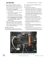
Build Your Output Cables:
Build two cables for output wiring.
1.
Output Terminals:
Use red, 8AWG cable
to build a “Y” cable with legs of equal length
(within 1/4-inch).
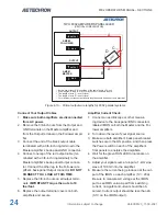
IMPORTANT: The legs of
this output cable must be of equal length
for proper system operation. See Figure 6.9.
Terminate each of the two legs of the cable
with 3/8-inch ring terminal ends to facilitate
connection to the system’s output connectors.
Terminate the “Y” end into a spade lug, ring ter
-
minal or other terminal suitable for the system
output and adaptable to the connectors on the
load. See
Figure 6.10.
2.
Ground Terminals:
Use black, 4AWG cable to
build a cable terminated at one end with a 3/8-
inch ring terminal to facilitate connector to the
master amplifier’s ground connector. Terminate
the other end into a spade lug, ring terminal or
other terminal suitabel for the system output
and adaptaqble to the connectors on the load.
Figure 6.9 – Output cable for 8302 parallel systems
Содержание 8302
Страница 2: ......

