96-8006123_11-03-2021
Information subject to change
17
8302 OPERATOR’S MANUAL – SECTION 6
6 Applications
6.1 Emergency Standby Switch or
Safety Interlock
The two 9-pin D-Sub connectors on the amplifier
back panel (Interlock A and Interlock B) can be
used to remotely place the amplifier in Standby
mode. This can provide a valuable safety feature,
such as in creating a safety interlock for a cabinet
in which one or more 8302 amplifiers are installed
or wiring an emergency stop switch to the cabinet
front or another accessible location.
The Remote Standby functions the same as the
amplifier’s front-panel Power switch by placing the
amplifier in Standby mode. When an 8302 amplifi
-
er is in Standby mode, the low-voltage transformer
is energized but the high-voltage transformers are
not. By using a Remote Standby switch, all ampli
-
fiers in a multi-amp system can quickly and reliably
be placed in Standby mode simultaneously. A Re
-
mote Standby switch also eliminates mechanical
wear on the amplifier’s front-panel Power switch.
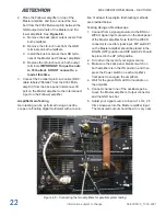
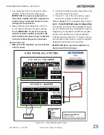
To use this function, wire a switch using PIn1 (Inter
-
lock) and either Pin 3 or Pin 6 (Ground), as shown
in
Figure 6.1
. Note that either the Interlock A con-
nector or the Interlock B connector can be used.
In multi-amp systems, the unused Interlock A
connector on the Master amplifier or the unused
Interlock B connector on the last Follower amplifier
can be used to wire the safety interlock.
6.2
Controlled-Voltage vs. Controlled-
Current Modes of Operation
AE Techron 8302 amplifiers can be field-configured
to operate as
Voltage Amplifiers
(Voltage-Con
-
trolled Voltage Source) or as
Transconductance
Amplifiers
(Voltage-Controlled Current Source).
The mode selection is made via the back-panel
DIP switch #4. See the
Advanced Configuration
section for more information.
When configured as a
Controlled-Voltage
source
(voltage amplifier), the amplifier will provide an
output voltage that is constant and proportional
to the control (input) voltage. If the load’s imped
-
ance changes, the amplifier will seek to maintain
this ratio of input to output voltage by increasing or
decreasing the current it produces, as long as it is
within the amplifier’s ability to create the required
current. Use this mode if you want the output volt
-
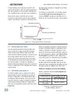
age waveform to be like the input waveform (see
Figure 6.2
).
9
9
1
1
Interlock
Interlock
Ground
Ground
REMOTE RUN/STANDBY
OR
S1
S1
Close to place amp in Standby mode;
open to place amp in Run mode.
Figure 6.1 – Using the Interlock A or Interlock B
connector to wire a safety interlock switch
Figure 6.2 – Input to Output Comparison,
Controlled-Voltage Operation
Conversely, when configured as a
Controlled-
Current
source (transconductance amplifier), the
amplifier will provide an output current that is con
-
stant and proportional to the control (input) volt
-
age. If the load’s impedance changes, the amplifier
will seek to maintain this transconductance (ratio
of input voltage to output current) by increasing or
decreasing the voltage it produces, as long as it is
within the amplifier’s ability to create the required
voltage. Use this mode if you want the output cur
-
rent waveform to be like the input waveform (see
Figure 6.3
).
Содержание 8302
Страница 2: ......

