background image

PPC-L126 User’s Manual

112

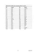
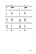
Table B.11: PCI/ISA pin assignments (Pins E and F)

Pin

Signal

Pin

Signal

E1

gnd

F1

GND

E2

gnd

F2

gnd

E3

int 1

F3

int3

E4

int 2

F4

int4

E5

v

cc

F5

v

cc

E6

---

F6

---

E7

v

cc

F7

v

cc

E8

PCIRST

F8

pclk2

E9

GNT1

F9

GND

E10

REQ1

F10

GNT2

E11

gnd

F11

gnD

E12

pclk1

F12

REQ2

E13

gnd

F13

ad31

E14

ad30

F14

ad29

E15

REQ3

F15

nc

E16

---

F16

---

E17

GNT3

F17

nc

E18

ad28

F18

ad27

E19

ad26

F19

ad25

E20

ad24

F20

cbe3

E21

ad22

F21

ad23

E22

ad20

F22

ad21

E23

ad18

F23

ad19

E24

nc

F24

PMF

E25

---

F25

---

E26

NC

F26

VSB3.3

E27

ad16

F27

ad17

E28

frame

F28

irdy

E29

cbe2

F29

devsel

E30

trdy

F30

lock

E31

stop

F31

perr

Содержание PPC-L126

Страница 1: ...PPC L126 VIA Eden Processor based Fanless Panel PC with 12 1 TFT LCD Users Manual...

Страница 2: ...al Inc VIA is a trademark of VIA Technologies Inc IBM PC AT PS 2 and VGA are trademarks of International Business Machines Corporation Intel and Pentium are trademarks of Intel Corporation Microsoft W...

Страница 3: ...ill no guarantee that interference will not occur If this equip ment is believed to be causing harmful interference to radio or television reception this can be determined by turning the equipment on...

Страница 4: ...amaged contact your distributor or sales representative immediately Additional Information and Assistance Step 1 Visit the Advantech web site at www advantech com where you can find the latest informa...

Страница 5: ...Maintenance to properly maintain and clean the surfaces use only approved products or clean with a dry applicator 5 CompactFlash Turn off power before insert ing or removing CompactFlash storage card...

Страница 6: ...y liquid into an opening This may cause fire or electrical shock 13 Never open the equipment For safety reasons the equipment should be opened only by qualified service personnel 14 If one of the foll...

Страница 7: ...eine Besch di gung vermieden 12 Durch die L ftungs ffnungen d rfen niemals Gegenst nde oder Fl ssigkeiten in das Ger t gelangen Dies k nnte einen Brand bzw elektrischen Schlag aus l sen 13 ffnen Sie...

Страница 8: ...PPC L126 User s Manual viii...

Страница 9: ...IOS Setup Program 13 2 4 Installing System Software 14 2 4 1 Method 1 Use the Ethernet 14 2 4 2 Method 2 Use the COM or parallel port 14 2 4 3 Method 3 Use a CD ROM 14 2 5 Installing the Drivers 15 Ch...

Страница 10: ...ion of Ethernet Driver 32 5 2 1 Installation for Windows 98 2000 ME 33 5 2 2 Installation for Windows NT 38 5 3 Further Information 40 Chapter 6 PCI SVGA Setup 42 6 1 Introduction 42 6 1 1 Chipset 42...

Страница 11: ...ower Management Setup 92 Figure 9 6 Power Management Setup 92 9 2 7 PnP PCI Configurations 93 Figure 9 7 PnP PCI Configurations 93 9 2 8 PC Health Status 93 Figure 9 8 PC Health Status 93 9 2 9 Freque...

Страница 12: ...t Connector CN11 107 B 8 VGA Connector CN2 108 Table B 8 VGA connector CN2 108 B 9 PCI ISA Bus connector Slot 1 109 Figure B 1 PCI ISA connector Side View 109 Table B 9 PCI ISA pin assignments Pins A...

Страница 13: ...CHAPTER 1 General Information This chapter gives background information on the PPC L126 panel PC Sections include Introduction General Specifications LCD Specifications Dimensions...

Страница 14: ...tion computer In addition its fit anywhere design makes it very flexible and able to be used in many different kinds of installations It can be wall mounted panel mounted or stood upright on a desktop...

Страница 15: ...cache memory on processor System Memory Two 168 pin DIMM sockets accept up to 1 GB SDRAM PCI bus master IDE interface Supports two connectors Each con nector has one channel and supports two IDE devi...

Страница 16: ...Frame buffer Supports 8 16 32 MB frame buffer w system memory Interface 4X AGP VGA LCD interface Support for 9 12 15 18 24 36 bit TFT and optional 16 or 24 bit DSTN panel Display mode CRT Modes 1600 x...

Страница 17: ...densing Shock 10 G peak acceleration 11 msec duration Certification EMC CE FCC VCCI BSMI Safety UL1950 and CB Vibration 5 500 Hz 1 G RMS Random vibration Type Analog Resistive Resolution Continuous Li...

Страница 18: ...50 000 hours Backlight lifetime 20 000 hours The VR control is defined by hot key in DOS or BIOS mode as below Ctrl Alt F3 Ctrl Alt F4 Note The color LCD display installed in the panel PC is high qua...

Страница 19: ...7 Chapter1 1 4 Dimensions Figure 1 1 Dimensions of PPC L126...

Страница 20: ...PPC L126 User s Manual 8...

Страница 21: ...Setup This chapter details system setup on the PPC L126 panel PC Sections include A Quick Tour of the Panel PC Installation procedures Running the BIOS Setup Program Installing System Software Instal...

Страница 22: ...When you place the panel PC upright on the desktop its front panel appears as shown in Figure 2 1 When you turn the panel PC around and look at its rear cover you will find the I O section as shown i...

Страница 23: ...11 Chapter2 Figure 2 2 Rear view of the panel PC Figure 2 3 Side view of the panel PC CompactFlash socket CFC eject button Compact CD ROM drive CD ROM activity light CD ROM eject button Speaker...

Страница 24: ...cord to the DC inlet of the panel PC 2 2 2 Connecting the keyboard or mouse Before you start the computer please connect the Y shaped adaptor to the PS 2 mouse and keyboard port on the I O section of...

Страница 25: ...such as the current date and time or your type of hard drive The setup program is stored in read only memory ROM It can be accessed either when you turn on or reset the panel PC by pressing the Del ke...

Страница 26: ...software requires an installed HDD Software can be loaded in the PPC L126 using any of four methods 2 4 1 Method 1 Use the Ethernet You can use the Ethernet port to download software to the HDD 2 4 2...

Страница 27: ...our system software you will be able to set up the Ether net SVGA audio and touchscreen functions All drivers are stored in a CD ROM disc entitled Drivers and Utilities which can be found in your acce...

Страница 28: ...PPC L126 User s Manual 16...

Страница 29: ...nstallation and Upgrading This chapter details installing the PPC L126 panel PC hardware Sections include Overview of Hardware Installation and Upgrading Installing the 2 5 Hard Disk Drive HDD Install...

Страница 30: ...rface The advanced IDE controller supports faster data transfer and allows the IDE hard drive to exceed 528 MB The following are instruc tions for installation 1 Detach and remove the plastic rear cov...

Страница 31: ...ter3 drive with Pin 1 on the cable corresponding to Pin 1 on the hard drive 5 Put the plastic rear cover on and tighten the screws Figure 3 1 Installing primary 2 5 HDD 2 5 HDD Metal plate Plastic rea...

Страница 32: ...bottom of PPC L126 2 Put the battery pack in then connect the battery cable to battery connector in the PPC L126 Make sure the red wire corresponds to Pin 1 on the connector 3 Close the battery door c...

Страница 33: ...instruc tions on setting jumpers and connecting peripherals switches and indicators Be sure to read all the safety precautions before you begin the installation proce dures Sections include Jumpers an...

Страница 34: ...nect them To close a jumper you connect the pins with the clip To open a jumper you remove the clip Sometimes a jumper will have three pins labeled 1 2 and 3 In this case you would connect either pins...

Страница 35: ...s the function of each of the board s jumpers 4 1 3 Locating jumpers and switch Table 4 1 Jumpers and their functions Label Function J1 LAN power type select J2 COM2 RS 232 422 485 setting J3 COM1 COM...

Страница 36: ...motherboard Label Function CN1 ATX power connector CN3 LVDS channel 1 connector CN4 Inverter power connector CN5 LVDS channel 2 connector CN8 Internal speaker connector Reserved CN12 Floppy drive conn...

Страница 37: ...25 Chapter4 Figure 4 2 Connectors on the PPC L126 motherboard...

Страница 38: ...tting 4 3 COM port interface J2 J3 J4 The panel PC provides four serial ports COM1 3 4 RS 232 COM2 RS 232 422 485 in one COM port connector 4 3 1 COM2 RS 232 422 485 setting J2 COM2 can be configured...

Страница 39: ...ial ports COM1 and COM2 are one set You can exchange the address range and interrupt IRQ of COM1 for the address range and interrupt IRQ of COM2 After exchanging COM1 s address range is 3F8 3FF and it...

Страница 40: ...ort Address Range Interrupt COM1 3F8 3FF IRQ4 COM2 2F8 2FF IRQ3 COM3 3E8 3EF IRQ10 COM4 2E8 2EF IRQ5 Table 4 6 COM1 2 3 4 pin 9 settings J3 Normal operation 5 V output 12 V output default setting Note...

Страница 41: ...adjust any jumper or switch to select the panel power 4 5 Watchdog Timer Configuration J4 An onboard watchdog timer reduces the chance of disruptions which EMP electromagnetic pulse interference can...

Страница 42: ...Wake on LAN select J1 The PCM L126 provides Wake on LAN function when ATX power is used To enable Wake on LAN function the J1 should be set as shown below Table 4 8 Wake on LAN select J1 Normal Power...

Страница 43: ...s Ethernet Inter face This chapter provides information on Ethernet configuration Sections include Introduction Installation of Ethernet Driver for Windows 98 2000 ME for Windows NT for Windows XP Fur...

Страница 44: ...hich can be enabled disabled in the BIOS setup 5 2 Installation of Ethernet Driver Before installing the Ethernet driver note the procedures below You must know which operating system you are using in...

Страница 45: ...5 5 2 1 Installation for Windows 98 2000 ME 1 a Select Start Settings Control Panel System b Click Device Manager and Other Devices c Double Click PCI Ethernet Controller 2 a Choose Driver b Click Upd...

Страница 46: ...PPC L126 User s Manual 34 3 Click Next 4 a Choose Display a list of all the drivers in a specific loca tion b Click Next...

Страница 47: ...35 Chapter5 5 a Select Network Adaptors b Click Next 6 a Click Have Disk...

Страница 48: ...8 b Click OK 8 a Choose Realtek RTL8139 810K Family PCI Fast Ethernet NIC 8 23 2001 b Click OK Note Installation for Windows 2000 please Type the path D PPC L126 Lan WIN2K Installation for Windows ME...

Страница 49: ...37 Chapter5 9 a Choose Next 10 a Click Finish...

Страница 50: ...PPC L126 User s Manual 38 5 2 2 Installation for Windows NT 1 Select Start Settings Control Panel and then double click the Network icon 2 a Select wire to the network b Click Next...

Страница 51: ...Chapter5 3 Press Have Disk 4 a Type the path D PPC L126 Lan NT40 b Press the OK button 5 a Choose the highlighted RTL8139 A B C 8130 PCI Fast Ether net Adapter b Click the OK button D PPC L126 Lan NT...

Страница 52: ...ok 7 Click Close 5 2 3 Installation for Windows XP Users are not required to install the Ethernet driver themselves 5 3 Further Information Realtek website www realtek com tw Advantech websites www a...

Страница 53: ...R 6 PCI SVGA Setup This chapter provides information on the PCI SVGA setup Sections include Introduction Installation of SVGA Drivers for Windows 98 2000 ME for Windows NT for Windows XP Further Infor...

Страница 54: ...ining complete IBM VGA compatibility Digital monitors i e MDA CGA and EGA are NOT supported Multiple frequency multisync monitors are handled as if they were analog monitors 6 1 2 Display memory The T...

Страница 55: ...lect Start Settings Control Panel System b Click the Device Manager and Display adapter items c Remove the Standard PCI Graphics Adapter VGA item d Click OK Notes 1 The windows illustrations in this c...

Страница 56: ...PPC L126 User s Manual 44 2 a Choose the Driver label b Click Update Driver 3 Click Next...

Страница 57: ...45 Chapter6 4 Click Next 5 Click Have Disk 6 a Type D PPC L126 VGA Win9x_ME b Click OK D PPC L126 VGA Win9x_ME...

Страница 58: ...00 please Type the path D PPC L126 Vga Win2000 in this step 7 Press Finish to reboot 6 2 2 Installation for Windows NT 1 a Select Start settings Control Panel b Double click the Display icon 2 a Choos...

Страница 59: ...47 Chapter6 3 Press the Change button 4 Click the Have Disk button 5 Click OK D PPC L126 Vga WinNT...

Страница 60: ...PPC L126 User s Manual 48 6 2 3 Installation for Windows XP 1 Select System Settings Control Panel and double click the system icon 2 Choose Hardware and Device Manager press OK button...

Страница 61: ...49 Chapter6 3 Choose Video Controller VGA Compatible press OK button 4 Choose Driver Update Driver press OK button...

Страница 62: ...PPC L126 User s Manual 50 5 Choose Install from a list press Next 6 Choose Don t search I will press Next button...

Страница 63: ...51 Chapter6 7 Choose Display adapters press Next button 8 Type the path D PPC L126 Vga WINXP then press OK button 9 Choose S3 Graphics Twister then press Next button D PPC L126 Vga WINXP...

Страница 64: ...ion For further information about the AGP VGA installation in your PPC L126 including driver updates troubleshooting guides and FAQ lists visit the following web resources VIA website www via com tw A...

Страница 65: ...CHAPTER 7 Audio Setup This chapter provides information on the Audio setup Sections include Introduction Installation of Audio Driver for Windows 98 2000 ME for Windows NT for Windows XP...

Страница 66: ...zer is register compatible with the OPL3 and has extended capabili ties 7 2 Installation of the Audio Driver Before installing the audio driver please take note of the procedures detailed below You mu...

Страница 67: ...tion for Windows 98 2000 ME 1 a Select Start Settings Control Panel and double click the System icon b Click the Device Manager and PCI Multimedia Audio Device items c Select Properties 2 Select Drive...

Страница 68: ...PPC L126 User s Manual 56 3 Click Next 4 Choose Display a list of all the drivers in a specific location then Click Next...

Страница 69: ...57 Chapter7 5 choose Sound video and game controllers click Next 6 Click Have Disk...

Страница 70: ...dio 98SE_Me_2K_XP Win98SE b Click OK Installation for Win 2000 type D PPC L126 Audio 98SE_Me_2K_XP Win2000 Installation for Win Me type D PPC L126 Audio 98SE_Me_2K_XP Win ME 8 Select VIA PCI Audio con...

Страница 71: ...59 Chapter7 9 Click Next 10 Click Finish...

Страница 72: ...7 2 2 Installation for Windows NT 1 Click Start and select Settings Click Control Panel and dou ble click Multimedia 2 In the Multimedia Properties window select the Devices tab Then select the Audio...

Страница 73: ...and click OK 4 When the Install Driver window opens put the utility disc in the CD drive Type D PPC L126 Audio WinNT Then click OK 5 In the Add Unlisted or Updated Driver window select the VIA PCI Au...

Страница 74: ...etting Change window click Restart Now 7 2 3 Installation for Windows XP After installing Windows XP the system can automatically detect the audio hardware and install the driver from the driver datab...

Страница 75: ...R 8 Touchscreen This chapter provides information on the touchscreen setup Sections include Introduction Installation of Touchscreen Drivers for Windows 98 ME for Windows NT for Windows 2000 for Windo...

Страница 76: ...ms incorporating the touchscreen controllers and cables have been approved to FCC Class A and Class B standards For more detailed information please visit the following websites www dynapro com or www...

Страница 77: ...To facilitate installation of the touchscreen driver you should read the instructions in this section carefully before you attempt installation Notes 1 The windows illustrations in this chapter are i...

Страница 78: ...r s Manual 66 8 2 1 Installation for Windows 98 ME 1 a Select Start Run b Type the path D Touchscreen Windows 98 Me Driver V2 1 Setup exe c Click OK 2 Click Next D Touchscreen Windows 98 Me Driver V2...

Страница 79: ...67 Chapter8 3 Click Yes to accept the agreement 4 Click Next...

Страница 80: ...PPC L126 User s Manual 68 5 Choose the directory then click Next 6 Click Next...

Страница 81: ...69 Chapter8 7 Click Next 8 Click Finish to complete the installation Then follow the instruction to reboot the computer...

Страница 82: ...6 User s Manual 70 8 2 2 Installation for Windows NT 1 a Select Start Run b Type the path D PPC L126 Windows NT Driver V1 0 02 Setup exe c Click Ok 2 Click Next D PPC L126 Windows NT Driver V1 0 02 Se...

Страница 83: ...71 Chapter8 3 Click Yes to accept the agreement 4 Click Next...

Страница 84: ...PPC L126 User s Manual 72 5 Choose the directory then click Next 6 Click Next...

Страница 85: ...73 Chapter8 7 Click Finish 8 Click Finish to complete the installation...

Страница 86: ...PPC L126 User s Manual 74 9 Click Detect to find the COM4 port as the touchscreen installa tion 10 Click Yes to reboot the system installation...

Страница 87: ...pter8 8 2 3 Installation for Windows 2000 1 a Select Start Run b Type the path D Touchscreen Windows 2000 XP Driver V2 0 Setup exe c Click OK 2 Click Next D Touchscreen Windows 2000 XP Driver V2 0 Set...

Страница 88: ...PPC L126 User s Manual 76 3 Click Next to accept the agreement 4 Click Install to start the installation...

Страница 89: ...8 5 Click Finish 6 After proceeding with the above procedures and rebooting the sys tem click Start Setting Control Panel select Add New Hardware then follow the instructions to complete the driver in...

Страница 90: ...our system please remove it first Follow the steps below to install the PenMount Windows 2000 XP driver 1 Please note that the installation procedures will be different depending on different computer...

Страница 91: ...age is not shown as Fig 1 then from Start select Control Panel select System select Hardware select Device Manager then double click the Unknown device 3 The next screen you should see is shown below...

Страница 92: ...Select Install from a list or specific location Advanced and click Next 5 Insert the PenMount DMC9000 drivers CD ROM select Search for best driver in these locations and choose Include this location i...

Страница 93: ...ed Click Finish 7 The screen will now show PenMount DMC9000 and DMC9100 under Mice and other pointing devices as shown below if your installation was successful Otherwise you need to go back to Step 1...

Страница 94: ...126 User s Manual 82 8 Please select the CD ROM to start installation 9 The screen displays copying installation wizard and PenMount Utilities Installation screen plus a welcome message appear Select...

Страница 95: ...83 Chapter8 10 The next screen is the Software License Agreement select I accept the terms is the license and click Next 11 The next screen is Ready to Install the Program Select Install...

Страница 96: ...ser s Manual 84 12 The next screen is InstallShield Wizard Completed and system asks to Reboot the system select Yes 13 After system reboot your touch system should be working now please Calibrate at...

Страница 97: ...CHAPTER 9 Award BIOS Setup This chapter describes how to set BIOS configuration data...

Страница 98: ...fatal errors Non fatal error messages usually appear on the screen along with the following instructions press F1 to RESUME Write down the message and press the F1 key to continue the bootup sequence...

Страница 99: ...nd the configuration informa tion has been erased The PPC L126 CMOS memory has an integral lithium battery backup The battery backup should last ten years in normal service but when it finally runs do...

Страница 100: ...dify the basic system configuration This type of information is stored in battery backed CMOS RAM so that it retains the Setup information when the power is turned off 9 2 1 Entering setup Power on th...

Страница 101: ...tup Screen menu the screen shown below is displayed This standard Setup Menu allows users to configure system components such as date time hard disk drive floppy drive and display Once a field is high...

Страница 102: ...Initial Setup Screen menu the screen below is displayed Users are not encour aged to run the BIOS and Chipset Features setup programs Your system should have been fine tuned before shipping Improper s...

Страница 103: ...Chipset Features option from the Initial Setup Screen menu the screen below is displayed Figure 9 4 Advanced Chipset Features setup Note It is strongly recommended that setup items in this section NO...

Страница 104: ...tial Setup Screen menu should produce the screen below Here we see the default values for the PPC L126 9 2 6 Power Management Setup By choosing the Power Management Setup option from the Initial Setup...

Страница 105: ...s option from the Initial Setup Screen menu the screen below is displayed 9 2 8 PC Health Status The PC Health Status option displays information such as CPU and moth erboard temperatures fan speeds a...

Страница 106: ...choosing the Frequency Voltage Control option from the Initial Setup Screen menu the screen below is displayed Figure 9 9 Frequency Voltage Control Warning Incorrect settings in Frequency Voltage Cont...

Страница 107: ...e Set Password option from the CMOS Setup Utility main menu and press Enter 2 When you see Enter Password enter the desired password and press Enter Figure 9 10 Load BIOS defaults screen Note To enabl...

Страница 108: ...then Enter To Disable Password 1 Choose the Set Password option from the CMOS Setup Utility main menu and press Enter 2 When you see Enter Password enter the existing password and press Enter 3 You wi...

Страница 109: ...97 Chapter9 9 2 13 Exit Without Saving Selecting this option and pressing Enter lets you exit the Setup pro gram without recording any new values or changing old ones...

Страница 110: ...PPC L126 User s Manual 98...

Страница 111: ...mer The PPC L126 is equipped with a watchdog timer that resets the CPU or generates an interrupt if processing comes to a standstill for any reason This feature ensures system reliability in industria...

Страница 112: ...t data is a time interval value The value range is from 01 hex to 3E hex and the related time interval is from 1 sec to 62 sec Data Time Interval 01 1 sec 02 2 sec 03 3 sec 04 4 sec 3E 62 sec After da...

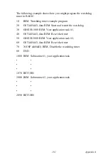
Страница 113: ...tart and restart the watchdog 30 GOSUB 1000 REM Your application task 1 40 OUT H443 data REM Reset the timer 50 GOSUB 2000 REM Your application task 2 60 OUT H443 data REM Reset the timer 70 X INP H44...

Страница 114: ...PPC L126 User s Manual 102...

Страница 115: ...Appendix B I O Pin Assignments...

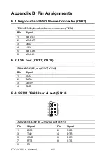
Страница 116: ...8 B 3 COM1 RS 232 serial port CN13 Table B 1 Keyboard and mouse connector CN20 Pin Signal 1 KB_DAT 2 MS DAT 3 GND 4 5 V 5 KB_CLK 6 MS CLK Table B 2 USB port CN17 CN18 Pin Signal 1 VCC 2 DATA 3 DATA 4...

Страница 117: ...5 COM4 RS 232 serial port CN16 Table B 4 COM3 RS 232 serial port Pin Signal Pin Signal 1 DCD 2 RXD 3 TxD 4 DTR 5 GND 6 DSR 7 RTS 8 CTS 9 RI Table B 5 COM3 RS 232 serial port Pin Signal Pin Signal 1 DC...

Страница 118: ...PPC L126 User s Manual 106 B 6 COM2 CN14 Table B 6 COM2 CN14 Pin Signal RS 232 RS 422 RS 485 1 DCD TX DATA 2 RX TX DATA 3 TX RX 4 DTR RX 5 GND GND 6 DSR 7 RTS 8 CTS 9 RI...

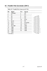
Страница 119: ...11 Table B 7 Parallel Port Connector CN11 Pin Signal Pin Signal 1 STROBE 2 D0 3 D1 4 D2 5 D3 6 D4 7 D5 8 D6 9 D7 10 ACK 11 BUSY 12 PE 13 SLCT 14 AUTOFD 15 ERR 16 INIT 17 SLCTINI 18 GND 19 GND 20 GND 2...

Страница 120: ...PPC L126 User s Manual 108 B 8 VGA Connector CN2 Table B 8 VGA connector CN2 Pin Signal 1 RED 2 GREEN 3 BLUE 4 N A 5 GND 6 GND 7 GND 8 GND 9 N A 10 GND 11 N A 12 SPDAT 13 HSYNC 14 VSYNC 15 SPCLK...

Страница 121: ...109 AppendixB B 9 PCI ISA Bus connector Slot 1 Figure B 1 PCI ISA connector Side View...

Страница 122: ...D1 B8 OWS A9 SD0 B9 12 V A10 IORDY B10 GND A11 AEN B11 SMW A12 SA19 B12 SMR A13 SA18 B13 IOW A14 SA17 B14 IOR A15 SA16 B15 DACK3 A16 SA15 B16 DRQ3 A17 SA14 B17 DACk1 A18 SA13 B18 DRQ1 A19 SA12 B19 RFS...

Страница 123: ...6 C2 la23 D2 io16 C3 la22 D3 irq10 C4 la21 D4 irq11 C5 la20 D5 irq12 C6 la19 D6 irq15 C7 la18 D7 irq14 C8 la17 D8 dacko C9 memr D9 drq0 C10 memw D10 dack5 C11 sd8 D11 drq5 C12 sd9 D12 dack6 C13 sd10 D...

Страница 124: ...IRST F8 pclk2 E9 GNT1 F9 GND E10 REQ1 F10 GNT2 E11 gnd F11 gnD E12 pclk1 F12 REQ2 E13 gnd F13 ad31 E14 ad30 F14 ad29 E15 REQ3 F15 nc E16 F16 E17 GNT3 F17 nc E18 ad28 F18 ad27 E19 ad26 F19 ad25 E20 ad2...

Страница 125: ...nal G1 NC H1 serr G2 NC H2 ad15 G3 cbe1 H3 ad14 G4 par H4 ad12 G5 gnd H5 gnd G6 H6 G7 gnd H7 gnd G8 ad13 H8 ad10 G9 ad11 H9 ad8 G10 ad9 H10 ad7 G11 cbeo H11 ad5 G12 ad6 H12 ad3 G13 ad4 H13 ad1 G14 ad2...

Страница 126: ...PPC L126 User s Manual 114...

Страница 127: ...ults 95 P Packing List iv Parallel Port 107 109 Part No 2008L12600 ii PC Health Status 93 PCI SVGA Setup 42 Pin Assignments 104 PnP PCI Configurations 93 Power cord 13 Power Management Setup 92 power...

Страница 128: ......

Отзывы: