15
Chapter 2
2.9 Solid State Disk
The PCM-9577 provides a CompactFlash™ card socket and DiskOnChip
socket for Solid state disk solutions.
2.9.1 CompactFlash (CN29)
The CompactFlash card shares a secondary IDE channel which can be
enabled/disabled via the BIOS settings.
2.10 Floppy drive connector (CN24)
You can attach up to two floppy drives to the PCM-9577’s on-board con-
troller. You can use any combination of 5.25” (360 KB and 1.2 MB) and/
or 3.5” (720 KB, 1.44 MB, and 2.88 MB) drives.
A 34-pin daisy-chain drive connector cable is required for a dual-drive
system. On one end of the cable is a 34-pin flat-cable connector. On the
other end are two sets of floppy disk drive connectors. Each set consists
of a 34-pin flat-cable connector (usually used for 3.5” drives) and a
printed-circuit board connector (usually used for 5.25” drives).
2.10.1 Connecting the floppy drive
1.
Plug the 34-pin flat-cable connector into CN24. Make sure that the
red wire corresponds to pin one on the connector.
2.
Attach the appropriate connector on the other end of the cable to
the floppy drive(s). You can use only one connector in the set. The
set on the end (after the twist in the cable) connects to the A: drive.
The set in the middle connects to the B: drive.
3.
If you are connecting a 5.25” floppy drive, line up the slot in the
printed circuit board with the blocked-off part of the cable connec-
tor.
If you are connecting a 3.5” floppy drive, you may have trouble determin-
ing which pin is number one. Look for a number printed on the circuit
board indicating pin number one. In addition, the connector on the floppy
drive may have a slot. When the slot is up, pin number one should be on
the right. Check the documentation that came with the drive for more
information.
If you desire, connect the B: drive to the connectors in the middle of the
cable as described above.
In case you need to make your own cable, you can find the pin assign-
ments for the board’s connector in Appendix C.
Содержание PCM-9577
Страница 1: ...i PCM 9577 Socket 370 Celeron Pentium III SBC with LCD LVDS Ethernet Audio USB 2 0 Users Manual...
Страница 10: ...PCM 9577 User s Manual x...
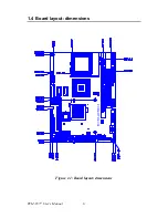
Страница 16: ...PCM 9577 User s Manual 6 1 4 Board layout dimensions Figure 1 1 Board layout dimensions PCM 9577 REV A1...
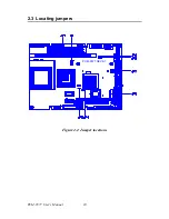
Страница 20: ...PCM 9577 User s Manual 10 2 3 Locating jumpers Figure 2 1 Jumper locations PCM 9577 REV A1...
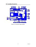
Страница 21: ...11 Chapter2 2 4 Locating Connectors Figure 2 2 Connectors component side PCM 9577 REV A1...
Страница 38: ...PCM 9577 User s Manual 28...
Страница 44: ...PCM 9577 User s Manual 34...
Страница 61: ...51 Chapter5 2 Choose the Adapter tab then press the Change button 3 Press the Have Disk button...
Страница 65: ...55 Chapter5 2 Select Adapter then Change...
Страница 66: ...PCM 9577 User s Manual 56 3 Press Next then Display a list 4 Press the Have disk button...
Страница 70: ...PCM 9577 User s Manual 60 2 Choose the Settings tab and press the Display Type button...
Страница 71: ...61 Chapter5 3 Press the Change button...
Страница 72: ...PCM 9577 User s Manual 62 4 Click the Have Disk button 5 Type the path D Biscuit VGA WinNT Press the OK button...
Страница 73: ...63 Chapter5 6 Select the highlighted item and click the OK button 7 Press Yes to proceed 8 Press OK to reboot...
Страница 75: ...65 Chapter5 2 Choose the Video Controller VGA Compatible button...
Страница 76: ...PCM 9577 User s Manual 66 3 Choose the Drive button press Update Driver button...
Страница 77: ...67 Chapter5 4 Choose Display a list of then press Next button 5 Choose Display adapters press Next button...
Страница 80: ...PCM 9577 User s Manual 70 2 Choose Hardware and Device Manager press OK button...
Страница 81: ...71 Chapter5 3 Choose Video Controller VGA Compatible press OK button...
Страница 82: ...PCM 9577 User s Manual 72 4 Choose Driver Update Driver press OK button 5 Choose Install from a list press Next...
Страница 83: ...73 Chapter5 6 Choose Don t search I will press Next button 7 Choose Display adapters press Next button...
Страница 86: ...PCM 9577 User s Manual 76...
Страница 101: ...91 Chapter6 3 Choose Driver button press Update Driver button 4 Choose Sound video and game controllers press Next...
Страница 103: ...93 Chapter6 8 Press Next button 9 Press Finish to reboot...
Страница 104: ...PCM 9577 User s Manual 94...
Страница 110: ...PCM 9577 User s Manual 100 7 2 3 Installation for Windows 2000 1 Open Device Manager...
Страница 111: ...101 Chapter7 2...
Страница 112: ...PCM 9577 User s Manual 102 3 4...
Страница 113: ...103 Chapter7 5 6...
Страница 114: ...PCM 9577 User s Manual 104 7 8...
Страница 115: ...105 Chapter7 9 7 2 4 Installation for Windows NT 1 a Select Start Settings Control Panel b Double click Network...
Страница 116: ...PCM 9577 User s Manual 106 2 a Choose type of network b Click Next 3 a Click Select from list...
Страница 118: ...PCM 9577 User s Manual 108 6 Check the highlighted item and click OK...
Страница 119: ...109 Chapter7 7 Click Next to continue setup 8 Choose the networking protocols then click Next...
Страница 120: ...PCM 9577 User s Manual 110 9 Select the correct Network Services then click Next 10 Click Next to continue setup...
Страница 122: ...PCM 9577 User s Manual 112...
Страница 126: ...PCM 9577 User s Manual 116...
Страница 127: ...Appendix B Installing PC 104 Modules This appendix gives instructions for installing PC 104 modules...
Страница 129: ...119 AppendixB Figure B 1 PC 104 module mounting diagram...
Страница 130: ...PCM 9577 User s Manual 120 Figure B 2 PC 104 module dimensions mm 0 1...
Страница 156: ...PCM 9577 User s Manual 146...
Страница 161: ...Appendix E Optional Extras for the PCM 9577...
Страница 165: ...Appendix F Mechanical Drawings...
Страница 167: ...157 AppendixF Figure F 2 PCM 9577 Mechanical Drawing solder side PCM 9577 REV A1...
Страница 168: ...PCM 9577 User s Manual 158...


