Appendix B
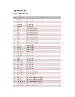
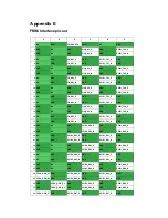
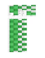
Zone 1 P10 Pin-out
Pin
pin name
Pin use
1 Reserved
No
connected
2
Reserved
No connected
3 Reserved
No
connected
4
Reserved
No connected
5
HA0
Hardware Address bit 0
6
HA1
Hardware Address bit 1
7
HA2
Hardware Address bit 2
8
HA3
Hardware Address bit 3
9
HA4
Hardware Address bit 4
10
HA5
Hardware Address bit 5
11
HA6
Hardware Address bit 6
12
HA7/P
Hardware Address bit 7
13 SCL_A
IPMB0-A
clock
14
SDA_A
IPMB0-A data
15 SCL_B
IPMB0-B
clock
16
SDA_B
IPMB0-B data
17 MT1_TIP
No
connected
18
MT2_TIP
No connected
19 RING_A
No
connected
20
RING_B
No connected
21 MT1_RING
No
connected
22
MT2_RING
No connected
23 RRTN_A
No
connected
24
RRTN_B-
No connected
25 SHELF_GND
Connect to shelf ground
26
LOGIC_GND
Connect to logic ground
27
ENABLE_B
Enable -48V_B power
28
VRTN_A
-48V return voltage VRTN_A input
29
VRTN_B
-48V return voltage VRTN_B input
30
-48V_EARLY_A
-48V pre-charge input for -48V_A
31
-48V_EARLY_B
-48V pre-charge input for -48V_B
32
ENABLE_A
Enable -48V_A power
Содержание MIC-5332
Страница 7: ...This page is left blank intentionally ...
Страница 10: ...Chapter 1 Product Overview This chapter briefly describes the MIC 5332 ...
Страница 15: ...Chapter 2 Board Features This chapter describes the MIC 5332 hardware features ...
Страница 43: ...Figure 3 10 Jumper Locations JP1 JP5 JP6 ...
Страница 44: ...Chapter 4 Hardware Management This chapter describes the IPMC firmware features ...
Страница 70: ...Chapter 5 AMI APTIO BIOS Setup This chapter describes how to configure the AMI APTIO BIOS UEFI BIOS ...
Страница 95: ...Chapter 6 Firmware Upgrade This chapter describes how to update the IPMC FW FPGA and BIOS for the MIC 5332 ...
Страница 105: ... root localhost ipmitool raw 0x2E 0x40 0x39 0x28 0x00 0x03 0x01 section ...
Страница 108: ...Appendix A IPMI PICMG Command Subset Supported by IPMC ...
Страница 120: ...33 48V_A 48V input feed A 34 48V_B 48V input feed B ...


