BC-N4 Glycol Chiller
Page: 44
ADVANTAGE ENGINEERING, INC.
525 East Stop 18 Road Greenwood, Indiana 46142
317-887-0729 Fax: 317-881-1277
Service Department Fax: 317-885-8683
Email: [email protected]
5.5 PUMP SEAL SERVICE
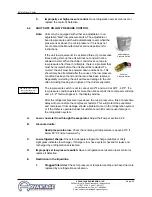
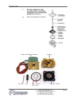
A.
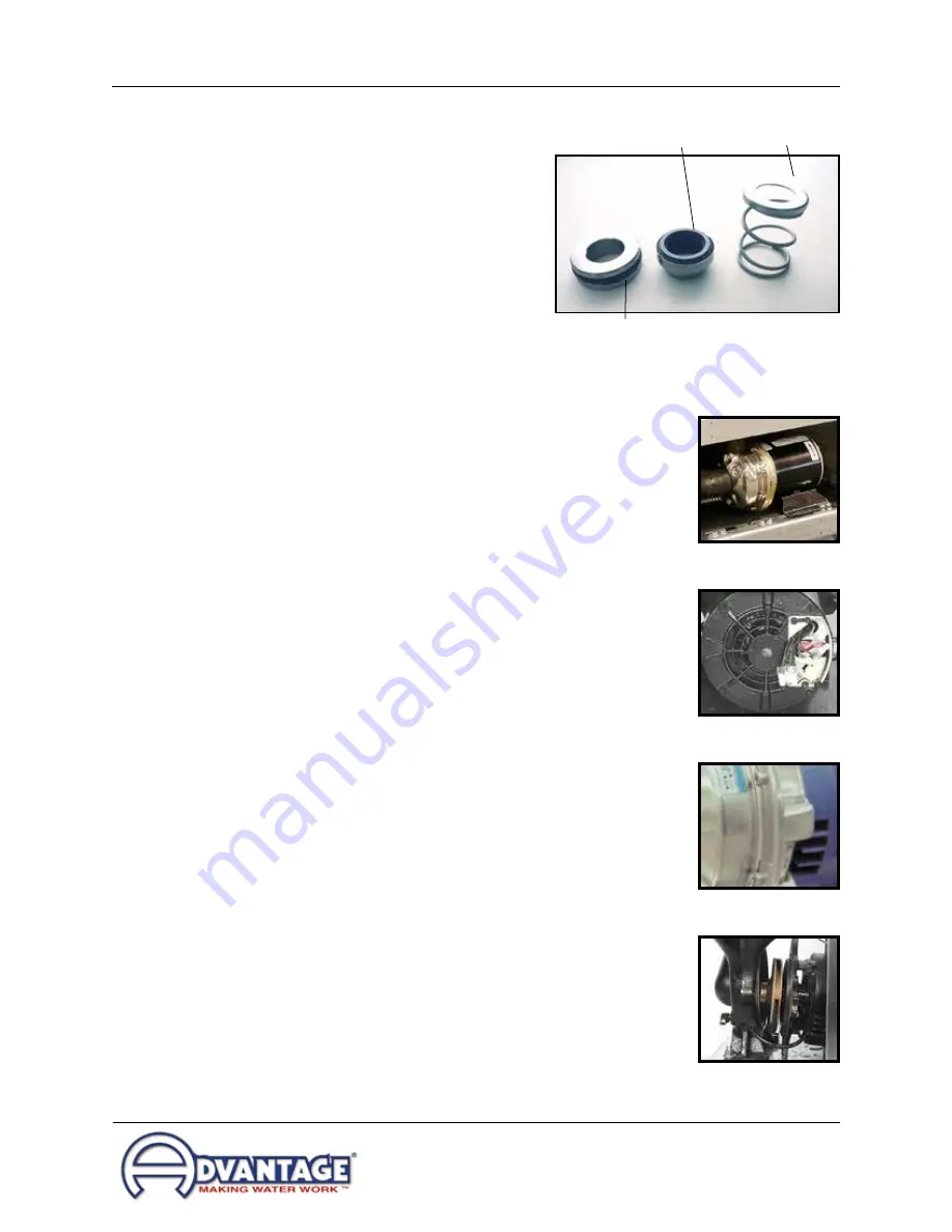
The coolant pump seal is a carbon/niresist
shaft seal assembly including a stationary
member, rotating member and tension
spring (figure 5.5A).
B.
The operator can determine the pump seal
is leaking when fluid is identified leaking
from the pump case adapter. Generally, a
pump seal will leak due to inadequate unit
pressure, excessive flow and poor fluid
quality.
C.
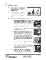
The operator should follow this procedure to replace the pump seal:
1.
Disengage process operations according to the procedure
outlined in section 3.4. The operator must be certain
process fluid temperature is under 100°F and pressure is
relieved (COOLANT pressure gauge reads “0”) and water
make-up flow is shut off and all pressure relieved.
2.
Disengage main power supply. The operator must verify
the proper lockout procedures are followed.
3.
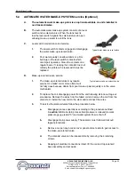
Access the pump motor by opening or removing any cover
panels as necessary (figure 5.5B).
4.
Drain machine. The machine can be drained by using
the drain valve located on the pump case. Drain fluid into
a suitable container for reuse or disposal according to
manufacturer’s instructions (if a glycol solution is used).
5.
Locate and remove the three motor wire leads from the
motor wiring terminals. The operator should “map” the wire
terminal locations to ensure correct rewiring. The power
cord should be removed from the motor housing (figure
5.5C).
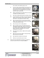
6.
Locate and remove the pump casing bolts. These bolts
secure the motor and motor adapter to the pump casing
(figure 5.5D).
7.
Separate the motor and motor adapter from the pump
casing to expose the pump impeller (figure 5.5E). Remove
the motor and motor adapter from the unit and place on a
workbench to continue the procedure.
8.
Locate and remove the dust cap from motor end to
expose slotted motor shaft. The motor shaft is free to
rotate, but must be secured to remove the impeller. To
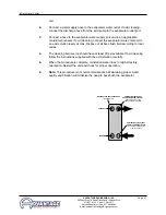
secure the motor shaft, insert a flat bladed screw driver in
Stationary member
Rotating Member
Tension Spring
Figure 5.5A
Typical Pump motor
Figure 5.5B
Casing Bolts
Figure 5.5D
Pump motor
Figure 5.5C
Separating Motor
Figure 5.5E
Содержание BC-N4 Series
Страница 2: ......
Страница 6: ...Page 6 THIS PAGE INTENTIONALLY BLANK ...
Страница 20: ...Page 20 THIS PAGE INTENTIONALLY BLANK ...
Страница 32: ...Page 32 THIS PAGE INTENTIONALLY BLANK ...
Страница 48: ...Page 48 THIS PAGE INTENTIONALLY BLANK ...
Страница 54: ...Page 54 THIS PAGE INTENTIONALLY BLANK ...
Страница 62: ...Page 62 THIS PAGE INTENTIONALLY BLANK ...
Страница 63: ...END 2016 ADVANTAGE ENGINEERING INC RE 09 27 2016 ...
Страница 64: ......

