background image

6


3.3.3.6 

ACPI 

Configuration 

.............................................................. 

45 


3.3.3.7 

USB 

Configuration 

............................................................... 

46 


3.3.4 Hardware Health Event Monitoring Screen .......................................... 47 


3.3.5 

Security 

Screen 

.................................................................................... 48 


3.3.6 

Boot 

Screen 

......................................................................................... 

49 


3.3.7 

Exit 

Screen 

........................................................................................... 51 

 3.4 

Software 

Support 

.......................................................................................... 

52 


3.4.1 Install Operating System ...................................................................... 52 


3.4.2 

Support 

CD 

Information 

....................................................................... 

52 


3.4.2.1 Running Support CD ........................................................... 52 


3.4.2.2 Drivers Menu ....................................................................... 52 


3.4.2.3 

Utilities 

Menu 

....................................................................... 

52 


3.4.2.4 

Contac 

Information 

.............................................................. 

52 


Содержание AES-1210 Series

Страница 1: ...1 1 AES 1210 Series User Manual ...

Страница 2: ...roducts described in this manual No part of this manual may be reproduced or copied without the prior written permission of Advanipc Technology Corporation Acknowledgements Microsoft Windows and MS DOS are registered trademarks of Microsoft Corp All other product names or trademarks are properties of their respective owners Printed in Taiwan AES 1210 Series User Manual Edition 1 2 March 2015 ...

Страница 3: ... table please contact your dealer immediately AES 1210 series system x 1 Phoenix Terminal Block 2 Pin Female x 1 only for DC input by 2 Pin models Rubber stand x 4 CD x 1 Drivers and User Manual Optional parts DC Adapter 50W or 60W with 2P Terminal Block and power cord DC Adapter 50W with DC Jack and power cord Wall Mount bracket x 2 with screws x 4 ...

Страница 4: ...ource is correct before connecting the equipment to the power outlet 7 All cautions and warnings on the equipment should be noted 8 If the equipment is not used for a long time disconnect it from the power source to avoid damage by transient overvoltage 9 Never pour any liquid into an opening This may cause fire or electrical shock 10 Never open the equipment For safety reasons the equipment shoul...

Страница 5: ... 15 2 4 HDMI 15 2 5 Ethernet LAN Connectors 16 2 6 USB Ports and Audio 16 2 7 mSATA and DRAM 17 2 8 SATA DOM 17 Chapter 3 SBC 210 IMB 18 3 1 Introduction 19 3 1 1 Specifications 20 3 1 2 Motherboard Layout 21 3 1 3 I O Panel 23 3 2 Installation 24 3 2 1 Screw Holes 24 3 2 2 Pre installation Precautions 24 3 2 3 Installation of Memory Modules DIMM 25 3 2 4 Expansion Slots 26 3 2 5 Jumpers Setup 27 ...

Страница 6: ...t Monitoring Screen 47 3 3 5 Security Screen 48 3 3 6 Boot Screen 49 3 3 7 Exit Screen 51 3 4 Software Support 52 3 4 1 Install Operating System 52 3 4 2 Support CD Information 52 3 4 2 1 Running Support CD 52 3 4 2 2 Drivers Menu 52 3 4 2 3 Utilities Menu 52 3 4 2 4 Contac Information 52 ...

Страница 7: ...7 Chapter 1 System Overview ...

Страница 8: ...re with Power Switch Power LED HDD LED and 4 USB 2 0 on front bezel AES 1210 series are with rich I O It has DC input by DC Jack or by 2 pin connector 2x USB 2 0 Line Out 2x USB 3 0 2LAN dual display VGA HDMI and Wi Fi feature by option ...

Страница 9: ...9 1 2 System Bottom Plate System equips a bottom plate on the down side of chassis It is friendly for DRAM mini PCIe full size mSATA module and mini PCIe half size devices installation and replacement ...

Страница 10: ...10 1 3 System Wall Mount Solution System equips an optional wall mount bracket to hang AES 1210 on the wall There are 4 holes from these two wall mount brackets to fix system on the suitable location ...

Страница 11: ...11 1 4 System Dimension The dimension of AES 1210 is 202mm W x 140mm D x 30mm H ...

Страница 12: ...12 Chapter 2 System Installation ...

Страница 13: ... provide a female 2 Pin phoenix connector showing as Figure 2 1 1 1 The DC voltage input range is from DC 9V to 36V Figure 2 1 1 1 DC Power Input 2 1 2 DC IN by DC Jack Besides the 2 Pin terminal block for DC source input system also equips a DC Jack showing as Figure 2 1 2 1 for DC power input The DC voltage input range is from DC 9V to 36V Figure 2 1 2 1 DC Jack ...

Страница 14: ...commodity devices Both are showed as Figure 2 1 3 1 And Figure 2 1 3 2 Figure 2 1 3 1 DC Adapter by 2 Pin Figure 2 1 3 2 DC Adapter by DC Jack 2 1 4 Power On System by Switch Before you are going to power on system please check your DC source is with correct connection Press the System Switch on front bezel left side showing as Figure 2 1 4 1 to power on system You could press system switch again ...

Страница 15: ... Pin Description List COM2 RS 232 Pin Description List Pin No RS 232 RS 422 RS 485 1 DCD TX RTX 2 RxD RX N A 3 TxD TX RTX 4 DTR RX N A 5 GND GND GND 6 DSR N A N A 7 RTS N A N A 8 CTS N A N A 9 NA 5V 12V N A N A Table 2 2 1 Pin List of COM1 COM2 2 3 VGA System supports a VGA output by D SUB 15 Pin connector 2 4 HDMI System supports a HDMI connector for display output ...

Страница 16: ...m supports two 10 100Mbps Ethernet port by two RJ 45 LAN connectors 2 6 USB Ports and Audio System provides 2 x USB 3 0 2 USB 2 0 type A ports and one line out audio port on rear I O System offers 4 x USB 2 0 type A ports on front bezel ...

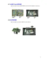
Страница 17: ...17 2 7 mSATA and DRAM System provides friendly SO DIMM DRAM and mSATA SSD installation maintenance 2 8 SATADOM System provides low profile SATADOM for space limitation ...

Страница 18: ...18 Chapter 3 SBC 210 IMB ...

Страница 19: ...the motherboard specifications and the BIOS software might be updated the content of this manual will be subject to change without notice In case any modifications of this manual occur the updated version will be available without further notice You may find the latest support lists on AdvanIPC Website http www advanipc com AdvanIPC FTP ftp www advanipc com If you require technology support relate...

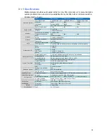
Страница 20: ...DMI Ethernet 2 x RJ45 USB Type A 2 x USB 3 0 2 x USB 2 0 Audio 1 x Audio ports Line out System Power Input 1 x DC Jack 9 36Vdc Input by DC Jack or by 2 pin phoenix Option front bezel Option COM3 4 DB 9 by request on front bezel Option GPIO 8 bit DB 9 by request on front bezel 4 x GPI 4 x GPO System Front Bezel Power On Button 1x Moment button switch to turn on system System Power LED 1x LED for sy...

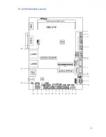
Страница 21: ...21 3 1 2 Motherboard Layout ...

Страница 22: ...Backlight Control Level BKT_PWR1 10 3 Pin Chassis FAN Connector 11 System Panel Header 12 SATA Power Output Connector 13 Clear CMOS Header 14 Digital Imput Output Pin Header 15 Digital Input Output Power Select 16 COM Port Header COM4 17 ATX AT Mode Selection 18 COM Port Header COM3 19 TPM Header 20 COM Port Header COM2 21 SET_CM1 22 COM Port Header COM1 23 Chassis Intrusion Headers CI1 CI2 24 PS2...

Страница 23: ...23 3 1 3 I O Panel There are two LED next to the LAN port Please refer to the table below for the LAN port LED ...

Страница 24: ...owing precautions before you install components into IMB or remove components from IMB or change any IMB settings 1 Unplug the power source from the wall socket before touching any component 2 To avoid damaging the motherboard components due to static electricity NEVER place your IMB directly on the carpet or the like Also remember to use a grounded wrist strap or touch a safety grounded object be...

Страница 25: ...R3 Double Data Rate 3 SO DIMM slot Step 1 Align a DIMM A on the slot such that the notch B on the DIMM matches the break on the slot Step 2 Firmly insert the DIMM A into the slot until the retaining clips C at both ends fully snap back in place and the DIMM A is properly seated ...

Страница 26: ...I Express Mini Card connector at a slightly upward angle Align the mounting holes and secure the card in place as E of the below figure 2 Mini PCIe mini SATA slot Mini PCIe mini SATA slot full size is used for PCI Express mini cards or mSATA cards SBC 210 is with A part as below figure Insert the full size card into the PCI Express Mini Card connector at a slightly upward angle Align the mounting ...

Страница 27: ... the system parameters to default setup please turn off the computer and unplug the power source After waiting for 15 seconds use a jumper cap to short pin2 and pin3 of CLRCMOS1 for 5 seconds However please do not clear the CMOS right after you updating the BIOS If you need to clear the CMOS when you just finish updating the BIOS you must boot up the system first and then shut it down before your ...

Страница 28: ...28 ...

Страница 29: ...29 3 2 6 Onboard Headers and Connectors ...

Страница 30: ...30 ...

Страница 31: ...31 ...

Страница 32: ...32 ...

Страница 33: ...nsert the support CD to your optical drive first Then the drivers compatible to your system can be auto detected and listed on the support CD driver page Please follow the order from top to bottom to install those required drivers Therefore the drivers you install can work properly ...
Страница 34: ...elete or by pressing the reset button on the system chassis You may also restart by turning the system off and back on 3 3 1 1 UEFI Menu Bar The top of the screen has a menu bar with the following selections Main To set up the system time date information Advanced To set up the advanced UEFI features H W Monitor To display current hardware status Boot To set up the default system device to locate ...

Страница 35: ...35 3 3 1 2 Navigation Keys Please check the following table for the function description of each navigation keys ...

Страница 36: ..._A1 Memory size of DIMM on SO DIMM slot System Date WEEK MONTH DAY YEAR System Time HOUR MINUTE SECOND NOTICE Please check the system date when you receive the IMB The system date should be correct because those data were adjusted before shipment Please contact with your dealer if the system date is not correct all the time ...
Страница 37: ...without entering operating systems first like MS DOS or Windows Just launch this tool and save the new UEFI file to your USB flash drive or hard drive then you can update your UEFI only in a few clicks without preparing an additional floppy diskette or other complicated flash utility Please be noted that the USB flash drive or hard drive must use FAT32 16 12 file system If you execute Instant Flas...

Страница 38: ... the current CPU does not support Intel SpeedStep technology CPU C States Support Enable CPU C States Support for power saving It is recommended to keep C3 enabled C6 and C7 disabled Enhanced Halt State C1E Enable or disable Enhanced Halt State C1E for lower power consumption N0 Excute Memory Protection No Execution NX Memory Protection Technology is an enhancement to the IA 32 Intel Architecture ...

Страница 39: ...he lines Intel Virtualization Technology When this option is set to Enabled a VMM Virtual Machine Architecture can utilize the additional hardware capabilities provided by Vanderpool Technology This option will be hidden if the installed CPU does not support Intel Virtualization Technology ...

Страница 40: ...nabled Panel Type Selection Use this to select panel type Onboard HD Audio Select Enabled or Disabled for the onboard HD Audio feature Onboard HDMI HD Audio This allows you to enable or disable the Onboard HDMI HD Audio feature Onboard LAN This allows you to enable or disable the Onboard LAN feature Onboard LAN 2 This allows you to enable or disable the Onboard LAN 2 feature Deep S5 This allows yo...

Страница 41: ...e power state after an unexpected AC power loss If Power Off is selected the AC power resumes off when the power recovers If Power On is selected the AC power resumes and the system starts to boot up when the power recovers The default value is Last State ...

Страница 42: ...TA mode Configuration options IDE Mode and AHCI Mode The default value is AHCI Mode SATA Aggressive Link Power Management Use this item configure SATA Aggressive Link Power Management Hard Disk S M A R T Use this item to enable or disable the S M A R T Self Monitoring Analysis and Reporting Technology feature Configuration options Disabled and Enabled ...

Страница 43: ...ect Technology Use this item to enable or disable Intel R Smart Connect Technology Intel R Smart Connect Technology keeps your e mail and social networks such as Twitter Facebook etc updated automatically while the computer is in sleep mode The default is Disabled ...

Страница 44: ... RS232 RS422 or RS485 COM2 Configuration Use this to set parameters of COM2 COM3 Configuration Use this to set parameters of COM3 COM4 Configuration Use this to set parameters of COM4 WDT Timeout Reset This allows users to enable disable the Watch Dog Timer timeout to reset system The default value is Disabled ...

Страница 45: ...Windows certification PS 2 Keyboard Power On Use this item to enable or disable PS 2 keyboard to turn on the system from the power soft off mode PCIE Devices Power On Use this item to enable or disable PCI devices to turn on the system from the power soft off mode RTC Alarm Power On Use this item to enable or disable RTC Real Time Clock to power on the system USB Keyboard Remote Power On Use this ...

Страница 46: ...his option to select legacy support for USB devices There are four configuration options Enable Auto Disabled and UEFI Setup Only The default value is Enabled Please refer to below descriptions for the details of these four options Enabled Enable support for legacy USB Auto Enable legacy support if USB devices are connected UEFI Setup Only USB devices are allowed to use only under UEFI setup and W...

Страница 47: ...t CPU_FAN1 s speed Configuration options Full On and Automatic Mode The default value is Full On CHA_FAN1 Setting This allows you to set CHA_FAN1 s speed Configuration options Full On and Automatic Mode The default value is Full On Case Open Feature This allows you to enable or disable case open detection feature The default is value Disabled Clear Status This option appears only when the case ope...

Страница 48: ... account Only the administrator has authority to change the settings in the UEFI Setup Utility Leave it blank and press enter to remove the password User Password Set or change the password for the user account Users are unable to change the settings in the UEFI Setup Utility Leave it blank and press enter to remove the password Secure Boot Enable to support Windows 8 Secure Boot ...

Страница 49: ... Prompt Timeout This shows the number of seconds to wait for setup activation key 65535 0XFFFF means indefinite waiting Bootup Num Lock If this item is set to On it will automatically activate the Numeric Lock function after boot up Boot Beep Select whether the Boot Beep should be turned on or off when the system boots up Please note that a buzzer is needed Full Screen Logo Use this item to enable...

Страница 50: ...ch PXE OpROM Policy Select UEFI only to run those that support UEFI option ROM only Select Legacy only to run those that support legacy option ROM only Launch Storage OpROM Policy Select UEFI only to run those that support UEFI option ROM only Select Legacy only to run those that support legacy option ROM only Launch Video OpROM Policy Select UEFI only to run those that support UEFI option ROM onl...

Страница 51: ...owing message Discard changes and exit setup Select OK to exit the UEFI SETUP UTILITY without saving any changes Discard Changes When you select this option it will pop out the following message Discard changes Select OK to discard all changes Load UEFI Defaults Load UEFI default values for all the setup questions F9 key can be used for this operation Launch EFI Shell from filesystem device Attemp...

Страница 52: ...ROM drive The CD automatically displays the Main Menu if AUTORUN is enabled in your computer If the Main Menu did not appear automatically locate and double click on the file SETUP EXE from the BIN folder in the Support CD to display the menus 3 4 2 2 Drivers Menu The Drivers Menu shows the available device s drivers if the system detects installed devices Please install the necessary drivers to a...

Отзывы: