background image


lead of the power cable and the desired positive voltage connection 
point.  
8. Route and connect the green lead to a convenient ignition switch 
supply point in the vehicle. 


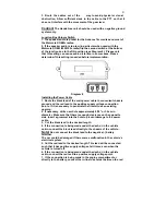
Diagram 5 

Stereo Mute 
If the vehicle’s stereo system supports an external muting feature, 
route and connects the orange wire to the car stereo system. 
Otherwise, the orange wire may be left unconnected and cut off or tied 
out of the way. 

NOTE!

 The Car Kit supports an “Entertainment Mute”  function when 

connected to a car stereo system that provides for external muting. 
This function is compatible with systems that mute the audio output 
when the control line is connected to ground 

Mounting the external vehicular Antenna 

1. Mount an external vehicular antenna (to be purchased separately) 
using the instructions provided with the manufacturer’s antenna kit.   

2. Position the antenna, maintaining a separation distance of at least 8 
inches (20 cms) between the antenna and the body of any user and 
nearby person, to assure compliance with the U. S. FCC regulations on 
RF exposure. 
3. Connect the coaxial antenna cable connector to the antenna cable   
connector from the Clam Cradle 
 
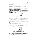
Mounting of the PTT - To the gear lever or flat surface 
1. To attach the PTT to the gear lever, strap the PTT around the gear 
lever (see diagram 4 using the Velcro strip attached, with the cord 
facing down.) 
2. To attach the PTT to a flat surface, remove the 2 screws from the 
bottom of the PTT, which holds the Velcro strip in place. Remove the 
strips and replace the small plastic part that held the strips in place 
with the larger flat plastic part supplied with the PTT. Screw the new 
plastic part in place. 


Diagram 6 


Содержание AT6538A

Страница 1: ...luded or purchased separately if not included to connect the car kit to the Motorola OEM cradle The adaptor cable is NOT required to connect the car kit to an AdvanceTec car kit cradle A properly installed Hands free Car Kit will minimize service calls and equipment downtime Because of the wide variations in vehicle design these instructions should be modified to suit each particular installation ...

Страница 2: ...e bench seat vs bucket seats Contact the vehicle manufacturer s corporate headquarters if necessary for specific air bag information for the vehicle make model and front compartment configuration involved in your communication equipment installation WARNING VEHICLES WITH ANTI SKID BRAKING SYSTEMS For vehicles with electronic anti skid braking systems refer to the Anti Skid Braking Precautions Moto...

Страница 3: ... vehicle or on the center side post between the front seats It must be protected from dirt and moisture and must be afforded adequate space for cooling There must be sufficient space to allow for connection of all cabling Diagram 2 2 Connect the Cradle Control Cable use the AdvanceTec connector cable referred to on page 1 of these instructions if a Motorola OEM cradle is being used the Speaker Mic...

Страница 4: ...upply voltage connection points If it is necessary to penetrate the firewall use an existing opening 2 If necessary drill a new hole approximately 9 16 or 3 5cm in diameter Make sure that there is enough clearance on the opposite side Insert a grommet into the hole to prevent damage to the power cable 3 Cut the black lead to the desired length 4 If the connection is being made under the dash or in...

Страница 5: ...ntenna to be purchased separately using the instructions provided with the manufacturer s antenna kit 2 Position the antenna maintaining a separation distance of at least 8 inches 20 cms between the antenna and the body of any user and nearby person to assure compliance with the U S FCC regulations on RF exposure 3 Connect the coaxial antenna cable connector to the antenna cable connector from the...

Страница 6: ...down inside the door molding Allow sufficient slack in the connector end of the cable to reach the Junction Box 3 Plug the connector side of the external microphone cord into the Junction Box as shown in diagram 3 above Note The microphone should not be mounted near a window or in a spot where road and ambient background noise would be substantially high Inserting and removing handset from cradle ...

Страница 7: ... microphone 4 Adjust the speaker volume using the handset s volume control 5 Incoming audio will be heard from the amplified speaker Making or receiving a hands free telephone call 1 To receive an incoming hands free telephone call press the SEND key any of the number keys the or key on the handset s keypad or the PTT button for a short period A confirmation tone that the call has been answered wi...

Страница 8: ... 2 A short press on the PTT will toggle between the calls 3 Pressing the PTT for more than 2 seconds will terminate the call Voice dialing in both Hands free mode and with Privacy handset With the handset in idle mode with or without the Privacy handset attached press the PTT for two seconds This will activate the voice dialing function Charging the battery 1 With the handset turned off the car ki...

Отзывы: