4
3. Route the cables out of the
way to avoid physical or visual
obstruction. Allow sufficient slack in the cable to the PTT so that it
does not interfere with the movement of the gear lever.
Caution!
The Hands-free unit should be used with a negative ground
system only
.
Junction Box Volume Switch
1. The speaker audio is preset for the AdvanceTec cradles and most of
the Motorola® OEM cradles.
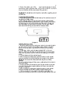
2. If the speaker audio is too low (in particular when used with the
Motorola® OEM i325/i355 cradle) flip the second switch at the bottom
of the junction box to the ON position (see Diagram 4). Please note
that this setting can cause audio distortion in some cases. Please
determine if this setting is needed before implementation.
Diagram 4
Installing the Power Cable
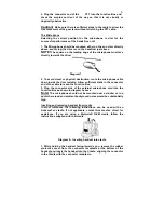
1. Route the black lead of the main power cable to convenient chassis
ground and the red lead to the positive supply voltage connection
points. If it is necessary to penetrate the firewall, use an existing
opening.
2. If necessary, drill a new hole approximately 9/16” or 3.5cm in
diameter. Make sure that there is enough clearance on the opposite
side. Insert a grommet into the hole to prevent damage to the power
cable.
3. Cut the black lead to the desired length.
4. If the connection is being made under the dash or in the vehicle
cabin, connect the black lead directly to the chassis of the vehicle..
Note!
Do not connect the black lead to the negative (-) battery
terminal.
The car could be damaged if there were a malfunction in the vehicle’s
electrical system.
5. Cut the red lead to the desired length. This lead will be connected
such that it has positive supply voltage at all times, even when the
vehicle is turned off.
6. If the connection is being made under the dash or in the vehicle
cabin, connect the red lead to a positive supply voltage point.
7. If the connection is being made in the engine compartment or
directly to the battery, connect the in-line fuse holder between the red


