2
Hardware installation
and Operation
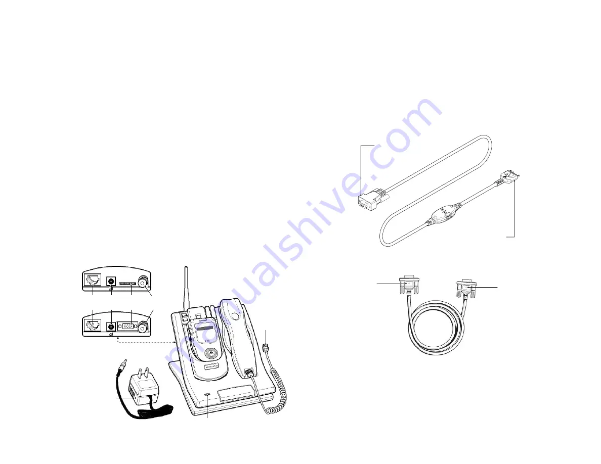
Install the communication kit according to the following steps:
Connecting the kit components
1
Position the AdvanceCommunicator™ in a convenient location at home
or office, next to an electric power supply that will allow connecting the
power adaptor to the AdvanceCommunicator™ base.
2
Connect the plug at the end of the handset cord to the handset socket
at the back of the AdvanceCommunicator™ base.
3
Connect the local antenna to the antenna port at the back of the
AdvanceCommunicator™ base.
4
Connect the power supply adaptor included in the kit to an electrical
socket next to the AdvanceCommunicator™ base location. Connect the
plug at the end of the power adaptor cord to the power socket, located
next to the handset socket, at the back of the AdvanceCommunicator™
base.
Handset
Plug
Power Adaptor
LED
Indicator
Antenna
Port
Power
Socket
Handset
Socket
Comm.
Socket
Falcon
(i730, i830, i833 and i860)
Condor
(i60, i90c and i95cl)
After connecting the AdvanceCommunicator™ base to the power
supply, the base station will perform a series of internal tests. During
these tests, the color of the LED indicator will change. At the end of the
test series, the LED indicator will display a flashing red signal.
5
In order to remote operate the AdvanceCommunicator™ from a
standard PC computer, connect one end of the Data Cable to the
Communication Socket at the back of the AdvanceCommunicator™
base, and the other, to a free serial port (COM) at the back of the
computer.
Connect to computer
serial port (COM)
Connect to base
Communication socket
Data Cable for Condor Phones (i60, i90c and i95cl)
Connect to computer
serial port (COM)
Connect to base
Communication socket
Data Cable for Falcon Phones (i730, i830, i833 and i860)
Note:
Please note that when connecting the Data Cable for Condor
phones (i60, i90c and i95cl) to the base Communication socket,
the Motorola "M" logo is facing
down
.


