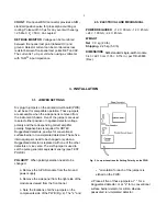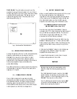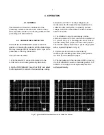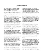
4
Fig. 3. Side-Panel Test Pulser Selection.
Damage may result to the preamplifier or the
detector unless the following precautions are
taken:
The TEST/BIAS/OFF switch must be in the OFF
position before connecting a low impedance or a
cable, capacitor, or other capacitive device to the
PREAMP IN connector on the A-PAD.
Turn the BIAS switch to OFF before making ANY
connections to the PREAMP IN connector and
before disconnecting the detector.
TEST PULSE The sixth jumper is used to set the
3.4. OUTPUT CONNECTIONS
equivalent energy of the test pulser to 5, 6, or 7 MeV.
Change this jumper only if an energy other than 5 MeV
When an external BNC cable longer than 10 ft is used
is desired from the test pulser. The jumper can be
for the output connection, the characteristic
changed through the hole in the side panel to an
impedance of the cable should match the impedance
alternate position (Fig. 3).
of the output used. The ENERGY output should use
3.2. CONNECTION TO DETECTOR
and trigger on the COUNT output. The output
A direct connection with 93-
6
or 100-
6
shielded cable
should be made between the detector and the
3. Adjust the front-panel E control for 8-V output.
PREAMP IN connector on the A-PAD. For best
Continue with operation of the A-576.
results, keep the length of this cable as short as
possible (due to the capacitive loading of the cable) to
minimize preamplifier noise and maintain the
preamplifier stability.
Type RG-62/U cable is recommended for the detector-
to preamplifier connection. This is 93-
6
cable with a
capacity of 13.5 pF/ft.
3.3. CONNECTION TO POWER
The A-PAD is designed for operation in a NIM-
standard bin and power supply such as the ORTEC
4001/4002/402 series. The power supply furnishes
operating power requirements at ±12 V and ±24 V.
These NIM bins have test points on the power supply
control panel to monitor the dc-voltage level.
93-
6
RG-62A/U cable, and the COUNT outputs
should be connected using 50-
6
RG-58A/U cable.
3.5. ENERGY OUTPUT FULL-SCALE
ADJUSTMENT (Other than 10 V)
The full-scale output from the ENERGY output is
normally set to 10 V, which matches the input range of
many multichannel analyzers (MCAs). The second
most common input range for MCAs is 8 V. The
procedure for 8-V full scale is as follows:
1. Set the TEST/BIAS/OFF switch to TEST. Set the
ENERGY RANGE switch to 3
&
5 MeV with the TEST
Pulser jumper set to 5 MeV. Note: Any Range can be
used when the TEST Pulser is set to the top of the
Range.
2. Observe the ENERGY output on an oscilloscope
amplitude should be about 10 V.
NOTICE
Содержание ORTEC A-576 A-PAD
Страница 4: ...iv ...


