NetVanta 6310/6330 Series Hardware Installation Guide
Physical Description
61700100G1-34F
Copyright © 2013 ADTRAN, Inc.
17
NetVanta 6310 Rear Panel Design
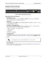
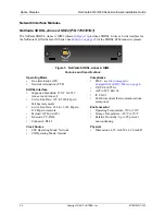
The NetVanta 6310 rear panel is shown below.
Figure 2. NetVanta 6310 Rear Panel Layout
NetVanta 6310 Rear Panel Interfaces
NIM2/VIM2 Option Slots
The two NIM2/VIM2 option slots (labeled
SLOT 1
and
SLOT 2
) accept a variety of NIM2/VIM2
option modules (refer to
Option Modules on page 23
).
PRI Interface
The PRI interface (labeled
PRI 0/1
) provides a single PRA/PRI/E1/T1 interface. See
Table A-3 on page
43
for the PRI interface pinouts.
10/100Base-T Ethernet Interfaces
The Ethernet ports (
ETH 0/1
and
ETH 0/2
) are RJ-45 connectors. See
Table A-2 on page 43
for the
Ethernet interface pinouts. The Ethernet ports provide the following:
• 10Base-T or 100Base-T with a single connector
• Auto negotiation
• CSMA/CD
• IEEE 802.3 compatibility
CONSOLE Interface
The
CONSOLE
interface is an EIA-232 serial port (DCE), which provides for local management and
configuration (via a DB-9 female connector). See
Table A-1 on page 43
for the
CONSOLE
interface
pinouts.
Power Connection
The rear panel has a power input to the AC universal power supply. Please refer to
Supplying Power to
the Unit on page 40
for connection details.
Connection directly to an external modem requires a cross-over cable.
SHDSL EFM ANNEX B
PRI 0/1
SLOT 2
SLOT 1
ETH 0/1
100-240 VAC
50/60 Hz
ETH 0/2


