background image

 Unit Installation

NetVanta 6310/6330 Series Hardware Installation Guide

 40

Copyright © 2013 ADTRAN, Inc.

61700100G1-34F

Supplying Power to the Unit

The NetVanta 6310/6330 Series units come equipped with an auto-sensing 100 to 240 VAC, 50/60 Hz power 
supply for connecting to a properly grounded power receptacle. (A detachable power cable with a grounded, 
three-prong plug comes with the shipment.) To power this unit, connect the power cable to an appropriate AC 
power source.

In addition to the equipment earthing conductor in the power supply cord, a 
supplementary equipment earthing conductor is to be installed between the system and 
earth. 

The supplemental earthing conductor shall be connected to the equipment using a 
number 8 ring terminal and should be fastened to the grounding lug provided on the 
rear panel of the equipment. The ring terminal should be installed using the 
appropriate crimping tool (AMP P/N 59250 T-EAD Crimping Tool or equivalent).

The supplementary equipment earthing conductor must not be smaller in size than 
cross-sectional area of not less than 2.5 mm

2

, if mechanically protected. The 

supplementary equipment earthing conductor is to be connected to the product at the 
terminal provided, and connected to earth in a manner that will retain the earth 
connection when the power supply cord is unplugged. The connection to earth of the 
supplementary earthing conductor must be in compliance with the appropriate rules for 
terminating bonding jumpers in Part K of Article 250 of the National Electrical Code, 
ANSI/NFPA 70, and Article 10 of Part 1 of the Canadian Electrical Code, Part 1, 
C22.1. Termination of the supplementary earthing conductor is permitted to be made 
to building steel, to a metal electrical raceway system, or to any earthed item that is 
permanently and reliably connected to the electrical service equipment earthed. 

Bare, covered, or insulated earthing conductors are acceptable. A covered or insulated 
conductor must have a continuous outer finish that is either green, or green with one or 
more yellow stripes.

A readily accessible disconnect device, that is suitably approved and rated, shall be 
incorporated in the field wiring.

Maximum recommended ambient operating temperature is 50

°

C.

Содержание NetVanta 6310

Страница 1: ...nex B NIM2 1700102G1 NetVanta Quad FXS VIM2 1700103G1 NetVanta Quad SHDSL EFM Annex A NIM2 1700103G2 NetVanta Quad SHDSL EFM Annex B NIM2 1700105G1 NetVanta Quad FXO VIM2 1700106G1 NetVanta Quad T1 E1...

Страница 2: ...of this publication Software Licensing Agreement Each ADTRAN product contains a single license for ADTRAN supplied software Pursuant to the Licensing Agreement you may a use the software on the purch...

Страница 3: ...0G1 34F Copyright 2013 ADTRAN Inc 3 Conventions Notes provide additional useful information Cautions signify information that could prevent service interruption or damage to the equipment Warnings pro...

Страница 4: ...5 The socket outlet shall be installed near the equipment and shall be easily accessible If any of the following conditions occur unplug the product from the electrical outlet and replace the part or...

Страница 5: ...to the telephone network or premises wiring using an FCC compatible modular jack which is compliant with Part 68 and requirements adopted by ACTA 7 The following information may be required when appl...

Страница 6: ...ss B EN 55022 Class B EN 55024 1700102G1 Quad FXS VIM2 FCC Part 15 Class B EN 55022 Class B EN 55024 FCC Part 15 Class B EN 55022 Class B EN 55024 1700103G1 Quad SHDSL EFM Annex A NIM2 FCC Part 15 Cla...

Страница 7: ...iques applicables aux appareils num riques de Class A prescrites dans la norme sur le materiel brouilleur Appareils Num riques NMB 003 edictee par le ministre des Communications Toll Fraud Liability B...

Страница 8: ...Service and Warranty NetVanta 6310 6330 Series Hardware Installation Guide 8 Copyright 2013 ADTRAN Inc 61700100G1 34F...

Страница 9: ...t Panel Design 18 NetVanta 6330 Rear Panel Design 18 NetVanta 6310 6330 Series Front Panel LEDs 19 Features and Specifications 21 Option Modules 23 Network Interface Modules 24 Voice Interface Modules...

Страница 10: ...Table of Contents NetVanta 6310 6330 Series Hardware Installation Guide 10 Copyright 2013 ADTRAN Inc 61700100G1 34F...

Страница 11: ...anta Quad SHDSL EFM Annex A NIM2 26 Figure 8 NetVanta Quad SHDSL EFM Annex B NIM2 27 Figure 9 NetVanta Quad T1 E1 EFM NIM2 28 Figure 10 NetVanta Ethernet NIM2 29 Figure 11 NetVanta Quad BRI S T NIM2 3...

Страница 12: ...List of Figures NetVanta 6310 6330 Series Hardware Installation Guide 12 Copyright 2013 ADTRAN Inc 61700100G1 34F...

Страница 13: ...A 3 PRI Connector Pinouts 43 Table A 4 FXO Connector Pinouts 44 Table A 5 VOICE Connector Pinouts 44 Table A 6 ADSL2 Pinouts 45 Table A 7 Ethernet Module Pinouts 45 Table A 8 SHDSL 2 Wire 4 Wire SHDS...

Страница 14: ...List of Tables NetVanta 6310 6330 Series Hardware Installation Guide 14 Copyright 2013 ADTRAN Inc 61700100G1 34F...

Страница 15: ...mation on shipping contents mounting options network and voice interface module installation and power the unit refer to the following sections Shipping Contents on page 16 Mounting Options on page 38...

Страница 16: ...ge If the equipment has been damaged in transit immediately file a claim with the carrier and contact ADTRAN Customer Service refer to the Support page on the ADTRAN website at http www adtran com sup...

Страница 17: ...hernet Interfaces The Ethernet ports ETH 0 1 and ETH 0 2 are RJ 45 connectors See Table A 2 on page 43 for the Ethernet interface pinouts The Ethernet ports provide the following 10Base T or 100Base T...

Страница 18: ...ash slot supplies nonvolatile configuration and compressed code storage CompactFlash densities from 64 to 1024 MB are supported Figure 3 NetVanta 6330 Series Front Panel Layout NetVanta 6330 Rear Pane...

Страница 19: ...etails NetVanta 6310 6330 Series Front Panel LEDs Table 1 describes the front panel LEDs Connection directly to an external modem requires a cross over cable Table 1 NetVanta 6310 6330 Series Front Pa...

Страница 20: ...d NIM2 has trained and is connected Green flashing NIM2 is training or initializing Amber solid NIM2 module is in test mode Red solid NIM2 is idle or is between training attempts SLOT 1 SLOT 2 EFM Mod...

Страница 21: ...remark DiffServ values on the ingress Router Features AOS based Stateful inspection firewall Quality of service QoS Network address translation NAT Dynamic Host Configuration Protocol DHCP client serv...

Страница 22: ...g Provides up to 30 channels of G 711 u Law Provides up to 30 channels of G 729 Provides up to 30 channels of dual tone multi frequency DTMF detection generation Supports 64 ms tail echo cancellation...

Страница 23: ...DSL EFM Annex A NIM2 P N 1700103G1 on page 26 NetVanta Quad SHDSL EFM Annex B NIM2 P N 1700103G2 on page 27 NetVanta Quad T1 E1 EFM NIM2 P N 1700106G1 on page 28 NetVanta Ethernet NIM2 P N 1700107G1 o...

Страница 24: ...ine termination CO Network termination CPE SHDSL Interface Supported Standards ITU T G 991 2 Annex A and Annex F 2 wire Line Rate 192 to 5696 kbps in 64 kbps increments 4 wire Line Rate 384 to 11 392...

Страница 25: ...tion CPE SHDSL Interface Supported Standards ITU T G 991 2 Annex Band Annex G ETSI TS101524 2 wire Line Rate 192 to 5696 kbps in 64 kbps increments 4 wire Line Rate 384 to 11 392 kbps in 128 kbps incr...

Страница 26: ...DSL EFM ANNEX A Features and Specifications Operating Mode Line termination CO Network termination CPE SHDSL Interface Four 2 wire eSHDSL loops Supported Standards ITU T G 991 2 Annex A ANSI T1 E1 4 2...

Страница 27: ...NNEX B Features and Specifications Operating Mode Line termination CO Network termination CPE SHDSL Interface Four 2 wire eSHDSL loops Supported Standards ITU T G 991 2 Annex B ETSI TS101524 IEEE 802...

Страница 28: ...4 Line Build Out 0 7 5 15 22 5 dB long 0 to 655 ft short Connector RJ 48C 4xE1 Interfaces Future Supported Standards ITU T G 703 ITU T G 704 CRC 4 ITU T G 823 ITU T G 797 Line Rate 2 048 Mbps 50 PPM L...

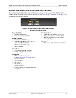
Страница 29: ...0 NetVanta Ethernet NIM2 10 100 BASE T ETHERNET Features and Specifications Ethernet Interface Supported Standards ITU T I 430 Auto MDI MDIX Auto Speed 10 100Base T Auto Duplex Connector RJ 45 Complia...

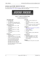
Страница 30: ...ce Supported Standards ITU T I 430 ANSI T1 605 ETSI ETS 300 012 Line Rate 196 kbps per interface Encoding Two B channels at 64 kbps one D channel at 16 kbps signaling and maintenance channels at 48 kb...

Страница 31: ...tandards ITU T G 992 1 Annex A ITU T G 992 3 Annex A ADSL2 ITU T G 992 5 Annex A ADSL2 ITU T G 992 3 Annex L READSL2 ITU T G 992 3 Annex M ANSI T1 413 Issue 2 Connector RJ 11C 6 pin jack inner pair Dy...

Страница 32: ...Four FXS ports Loop Start LS Ground Start GS Normal and reverse battery operation Transmission Level FXS Receive Gain 12 to 6 dB 0 1 dB steps FXS Transmit Gain 12 to 6 dB 0 1 dB steps Impedance 600 60...

Страница 33: ...FXS Receive Gain 6 to 10 dB 0 1 dB steps FXS Transmit Gain 6 to 10 dB 0 1 dB steps Impedance 600 600 2 16 F 900 900 2 16 F Rs 220 Rp 820 Cp 115 nF Rs 270 Rp 750 Cp 150 nF Rs 270 Rp 750 Cp 150 nF Zin 6...

Страница 34: ...Start LS Ground Start GS Normal and reverse battery operation Transmission Level FXS Receive Gain 12 to 6 dB 0 1 dB steps FXS Transmit Gain 12 to 6 dB 0 1 dB steps Impedance 600 600 2 16 F 900 900 2...

Страница 35: ...ceive Gain 6 to 10 dB 0 1 dB steps FXO Transmit Gain 6 to 10 dB 0 1 dB steps Impedance 600 600 2 16 F 900 900 2 16 F Rs 220 Rp 820 Cp 115 nF Rs 270 Rp 750 Cp 150 nF Rs 270 Rp 750 Cp 150 nF Zin 600r Rs...

Страница 36: ...ve Gain 6 to 10 dB 0 1 dB steps FXO Transmit Gain 6 to 10 dB 0 1 dB steps Impedance FXS 600 600 2 16 F 900 900 2 16 F FXO 600 600 2 16 F 900 900 2 16 F Rs 220 Rp 820 Cp 115 nF Rs 270 Rp 750 Cp 150 nF...

Страница 37: ...ified service personnel only and should be installed in a restricted access location as described in UL IEC 60950 1 Ethernet cables are intended for intrabuilding use only Connecting an ADTRAN unit di...

Страница 38: ...ration of the equipment is not compromised Be careful not to compromise the stability of the equipment mounting rack when installing this product Consideration should be given to the connection of the...

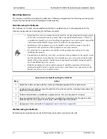
Страница 39: ...th the bottom of the chassis Reattach the mounting ears to the chassis see Figure 18 2 Decide on a location for the NetVanta keeping in mind that the unit needs to be mounted at or below eye level so...

Страница 40: ...smaller in size than cross sectional area of not less than 2 5 mm2 if mechanically protected The supplementary equipment earthing conductor is to be connected to the product at the terminal provided a...

Страница 41: ...e wrist strap to prevent damage to electrical components Place modules in antistatic packing material when transporting or storing When working on modules always place them on an approved antistatic m...

Страница 42: ...r a specific application refer to the configuration guides provided online on ADTRAN s Support Forum For details on the CLI refer to the AOS Command Reference Guide All other related documents are als...

Страница 43: ...t 2 RD Receive Data output 3 TD Transmit Data input 4 DTR Data Terminal Ready input 5 SG Signal Ground 6 DSR Data Set Ready output 7 RTS Request to Send input 8 CTS Clear to Send output 9 Unused Table...

Страница 44: ...p 8 33 Circuit 8 FXS 0 8 Ring Tip 9 34 Circuit 9 FXS 0 9 Ring Tip 10 35 Circuit 10 FXS 0 10 Ring Tip 11 36 Circuit 11 FXS 0 11 Ring Tip 12 37 Circuit 12 FXS 0 12 Ring Tip 13 38 Circuit 13 FXS 0 13 Rin...

Страница 45: ...Pinouts Pin Name Description 1 TR Transmit Positive 2 TR Transmit Negative 3 RX Receive Positive 4 5 Unused 6 RX Receive Negative 7 8 Unused Table A 8 SHDSL 2 Wire 4 Wire SHDSL EFM Ports 1 and 2 Pino...

Страница 46: ...Name Description 1 RX Ring Receive 2 RX Tip Receive 3 Unused 4 TX Ring Transmit 5 TX Tip Transmit Table A 11 BRI S T Module Pinouts Pin Name Description 1 2 Unused 3 Receive Receive 4 5 Transmit Tran...

Отзывы: