background image

2

61287802F1-13F

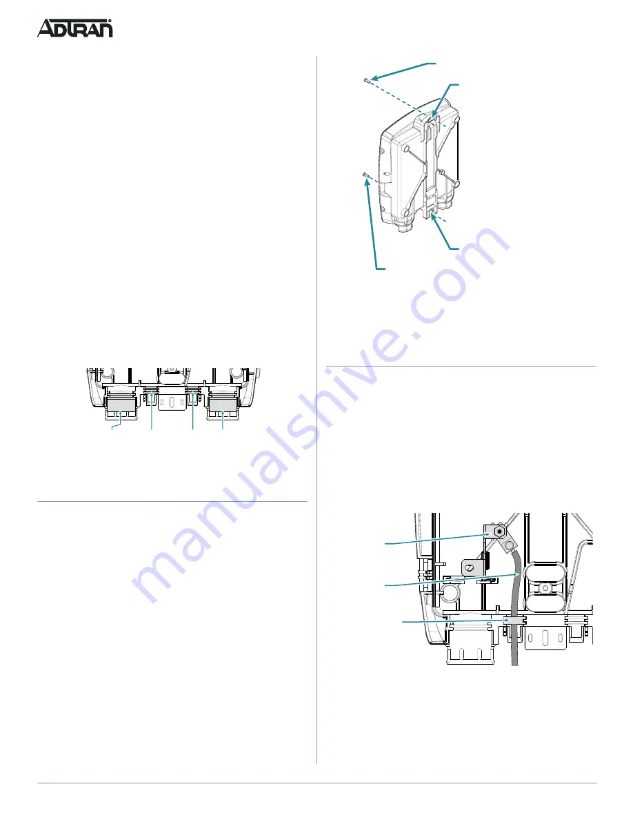
Figure 2. Mounting Hole Location

3. Pre-drill the marked locations and install fasteners or anchors 

appropriate to the mounting surface (each anchor rated to 

15 lbs. minimum).

4. Mount the NID to the side of the subscriber’s premise.

Ground the NID

Install the ground connection by completing the following steps 
(refer to 

Figure 3

 for ground cable routing):

f


CAUTION!

Do not use a knife to cut the opening in the ports. This can result in 
an excessively large hole and compromise the integrity of the unit 
and allow moisture into the unit.

1. Refer to 

Figure 3

 and insert the ground wire through the port.

2. Remove 1 inch of the insulation jacket from a 6 AWG 

minimum copper ground wire.

Figure 3. Inserting the Ground Wire

3. Loosen the set screws on the ground bar.
4. Insert the ground wire in the ground bar and tighten set screw.
5. Route the ground wire 12 inches below finished grade by the 

shortest and most direct route to the AC power ground system 
to connect to a ground. Ensure the wire is free of any sharp 
bends.

Rear View

Top Mounting Hole

Top Mounting Screw

Bottom Mounting Hole

Bottom Mounting Screw

Ground Bar

Ground Wire

Rubber Grommet

Included with the GPON 452/454 packaging are 2/4 Two-screw 
Terminal Bridges (2 for the 452 and 4 for the 454); an SC/APC fiber 
jumper; and a 7-position power and alarm connector. For data, the 
connection to the ONT is through the RJ-45 Ethernet connector. 
For POTS, the connection is made through 2/4 Two-screw Terminal 
Bridges (2 for the 452 and 4 for the 454) or RJ-11 connections. 

Installation Steps

To install the ONT, complete the following steps:

“Mount the NID Enclosure”

“Ground the NID”

“Install the ONT”

“Route the Fiber Connection”

“Connect Power/Alarm”

“Install a Local Power Source”

“Install the UPS”

“Connect Subscriber Services”

“Connect Ethernet to the ONT”

NID Port Identification

The NID has four input ports for service entry. Each port is 
equipped with a grommet to provide protection from the elements. 
Each port is identified in 

Figure 1

.

Figure 1. NID Port Identification

Mount the NID Enclosure

Complete the following steps to mount the enclosure:

f


WARNING!

This equipment must be connected to a known, reliable earth 
ground at all times during installation and service. This product 
is intended for installation only in UL Listed enclosure QVGV 
suitable for outdoor use CORNING

® 

CABLE SYSTEMS Inc., 

Model FNI-NG1-U1010 or FNI-NG1-U0110.

This equipment must be serviced by authorized service 
personnel only.

1. Choose a vertical surface near an approved ground, but away 

from down spouts, permanent water sprinklers, or other water 
sources. The subscriber should have easy access for testing.

2. Refer to 

Figure 2

 and use the top and bottom Mounting Holes 

as a template to mark fastener locations. Use a level to 
ensure the unit is level to prevent warping.

Phone

Ethernet

Video

Fiber Drop

Cable

Ground Cable
Power Supply

Customer

Port

Содержание 1287802F1

Страница 1: ...SS 1 LASER PRODUCT INSTALLATION This section explains how to install the NID ground the NID route and attach the incoming Fiber and install the ONT in the NID There is also a section on connecting POTS and Ethernet services After unpacking the ONT inspect it for damage If damage is noted file a claim with the carrier and then contact ADTRAN For more information refer to the warranty f WARNING Read...

Страница 2: ...data the connection to the ONT is through the RJ 45 Ethernet connector For POTS the connection is made through 2 4 Two screw Terminal Bridges 2 for the 452 and 4 for the 454 or RJ 11 connections Installation Steps To install the ONT complete the following steps Mount the NID Enclosure Ground the NID Install the ONT Route the Fiber Connection Connect Power Alarm Install a Local Power Source Install...

Страница 3: ...Splice SC APC Bulkhead NID P N 1187770G1 g NOTE Clean all optical surfaces before connecting cables OptiTap NID P N 1187771G1 To install the fiber connection using the Optical Connector refer to Figure 5 and complete the following steps Figure 5 Optical Connector 1 Route the incoming fiber cable through the port identified in Figure 1 2 Connect the optical connector 3 Connect a fiber jumper from t...

Страница 4: ... 9 Power Alarm Connection and Routing 3 Terminate the 2 power leads Pins 6 and 7 and the five Uninterruptible Power Supply UPS leads see the pinout table 4 Connect the Power Alarm connector to the bottom of the ONT refer to Figure 8 5 Tie wrap and route these wires as shown in Figure 10 This will prevent the connector from coming loose when the ONT is closed Figure 10 Power Alarm Connector Install...

Страница 5: ...in any other fashion may cause harmful interference to radio communications ans is in violation of the FCC Rules part 15 CLEI TEL NUMBER PWR GPON POTS1 POTS2 POTS3 POTS4 Ethernet Connections POTS Connections Two Post Bridge Cable Routing Area POTS and Ethernet Port Captive Screw 2 Trim each wire to length 3 Connect the tip and ring wires to the terminal bridges 4 Insert the RJ 11 connectors from t...

Страница 6: ...r dial tone and flashes the GPON LED green for approximately 10 seconds with a cadence of 300 milliseconds on off before it continues its startup ranging process g NOTE If a failure occurs the ONT plays reorder tone and displays Invalid on the caller id display If the pattern is entered incorrectly the caller id displays Re enter if the first ID does not match the second Entering an invalid Regist...

Отзывы: