38
Operation Theory
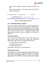
clock. Feeding the clock source into a frequency divider generates
the ADC sampling frequency. The following formula determines
the ADC sampling frequency:
Sampling Rate = Frequency of Source Clock / ADC Clock Divisor
Note that the ADC Clock Divisor = 2,4,6,8,10… 65534 (maximum)
External Pacer Clock
Users can connect an external pacer clock to the EXTCLK1 (pin 1)
on JP1 (for square wave) or Ext. Sine wave clock (for sine wave).
Because users can handle the external signal with outside
devices, the conversion rate of this mode is more flexible than the
previous mode. When external clock is selected, the frequency
divider as mentioned also divides this external clock. Therefore
the frequency of the external clock should be at least twice the
sampling frequency. The formula is shown below:
Sampling Rate = Frequency of Source Clock / ADC Clock Divisor
Multiple Cards Operation
When multiple cards are used in one system, 4-channels on one
card can achieve simultaneous conversion because of the same
internal clock source. However, the channels between two cards
cannot be synchronized because the clock sources on different
cards come from different sources. Even when the same external
clock source is applied to all cards, the A/D conversion time is still
possibly asynchronous because an onboard clock divider (divided
Note:
1.The clock divider must be an even number, that is,
the ADC Clock Divisor = 2, 4, 6, 8, 10… 65534 (max.),
with the minimum divider value being 2. Please refer to
section 6.2 to set the clock source and frequency
divider.
2.Because of the pipelined architecture of the ADC,
the first AD sample takes several clocks to convert.
Therefore, the external clock must be continuous for
correct AD operation.
Содержание NuDAQ PCI-9810
Страница 4: ......
Страница 10: ...vi ...
Страница 19: ...Installation 9 2 3 PCI 9812 10 s Layout Figure 2 1 PCB Layout of the PCI 9812 10 ...
Страница 22: ...12 ...
Страница 40: ...30 ...
Страница 78: ...68 Software Utility ...

